Instructions
Everything you need to set up your FaceFocusVR kit. Read each step carefully and take your time.
If you need any help, join the Discord
Before You Begin
Installing the kit is mostly straightforward and should take roughly one to two hours if you follow the instructions carefully, thoughtfully, and at your own pace. There is no need to rush.
The instructions in this guide describe the method I have found to be the most reliable and easiest to install. If you discover a better approach during installation, for example a different cable routing method, you are free to use it. That said, I strongly recommend following my instructions exactly as written, especially on your first attempt.
Regardless of your chosen approach, please keep one important rule in mind: camera cables must never be kinked, twisted, or folded. Gentle bends are perfectly fine, but the cables must remain smooth and free of sharp angles at all times. Damaged cables cannot be repaired and will need to be replaced.
-
Board Connector Overview
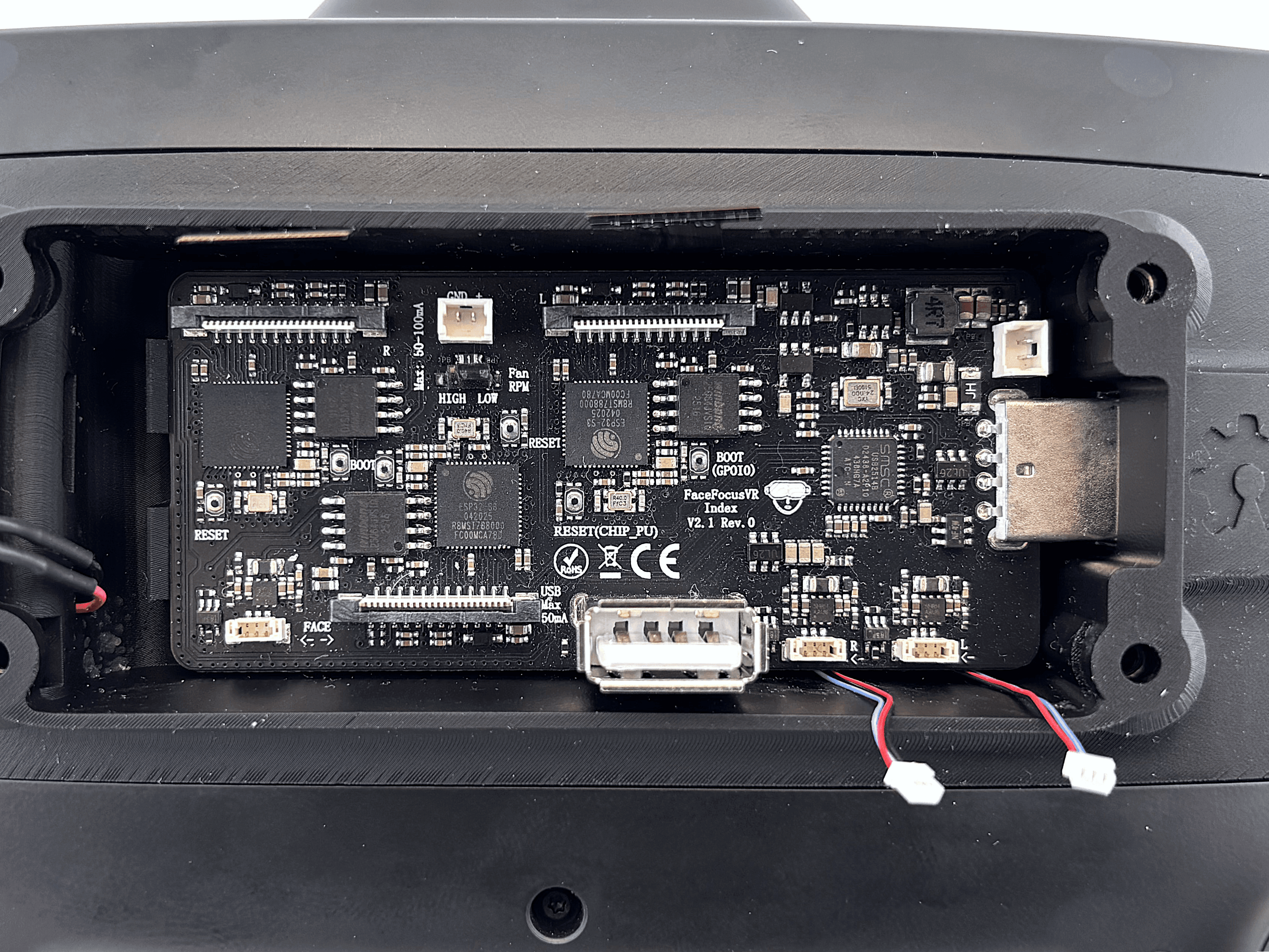
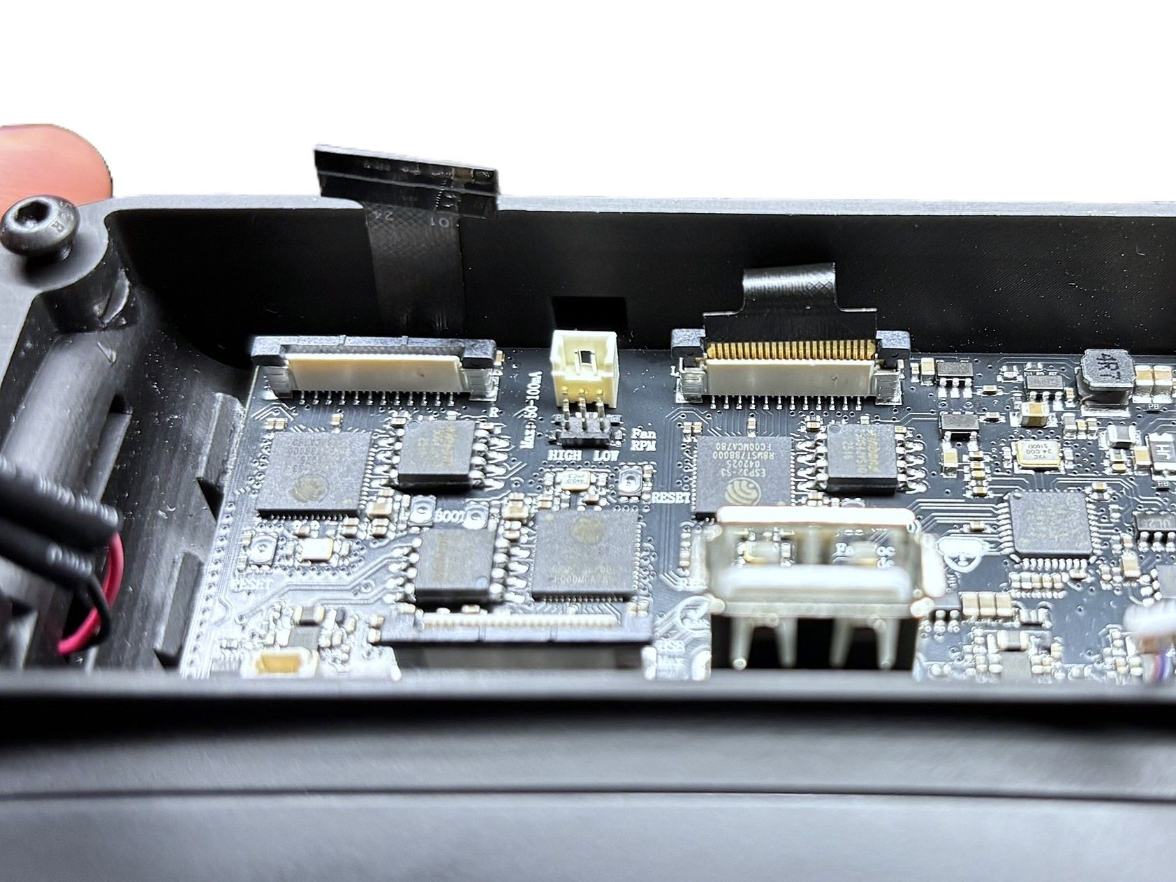
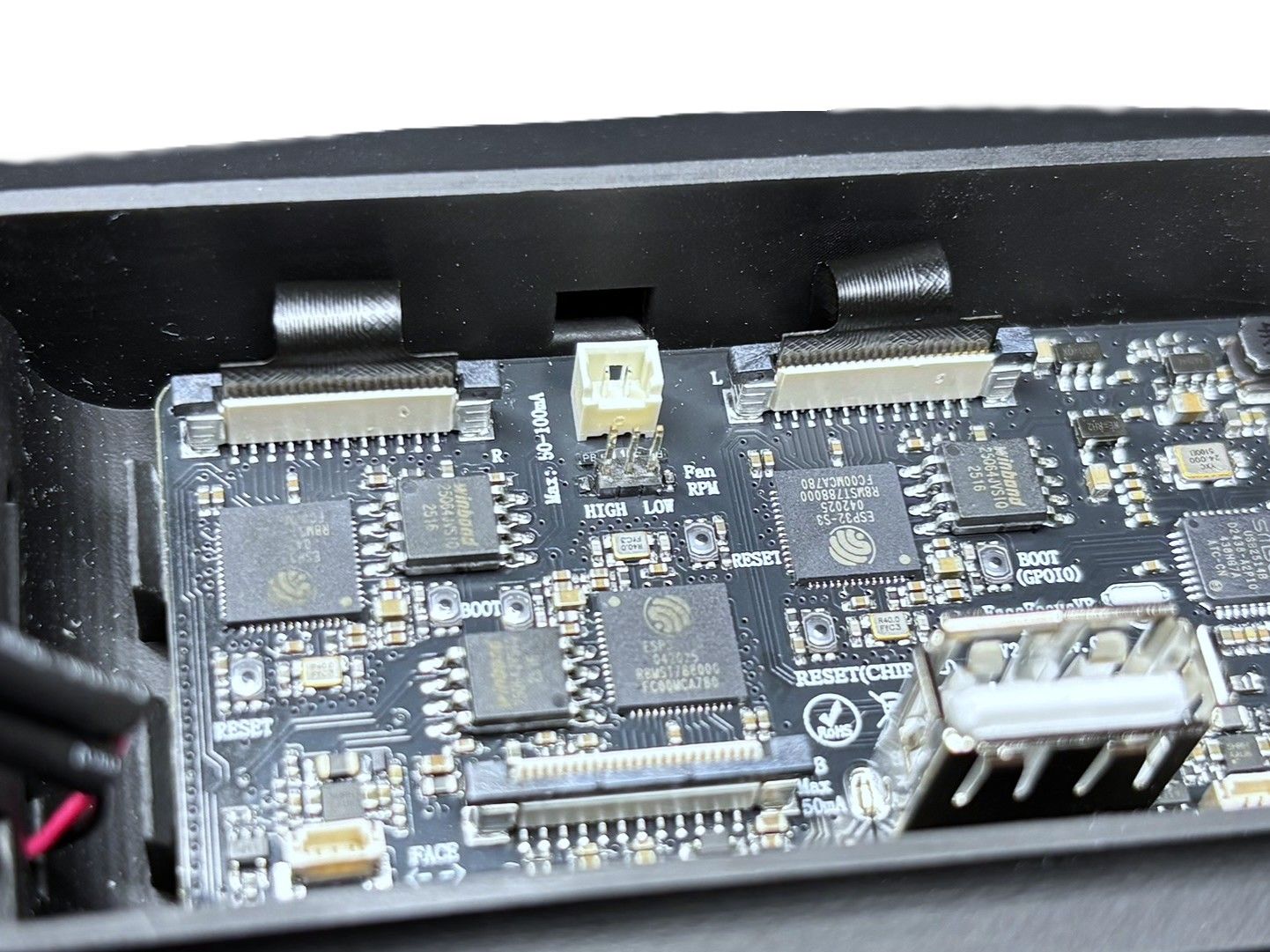
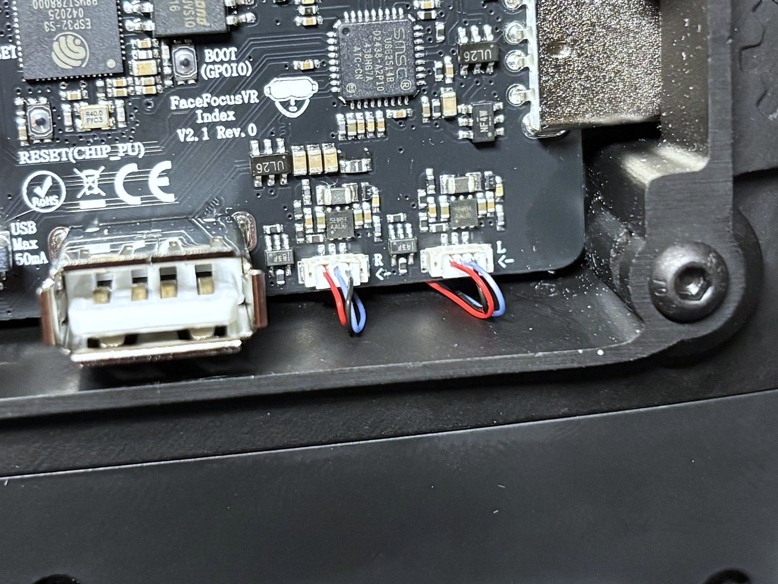
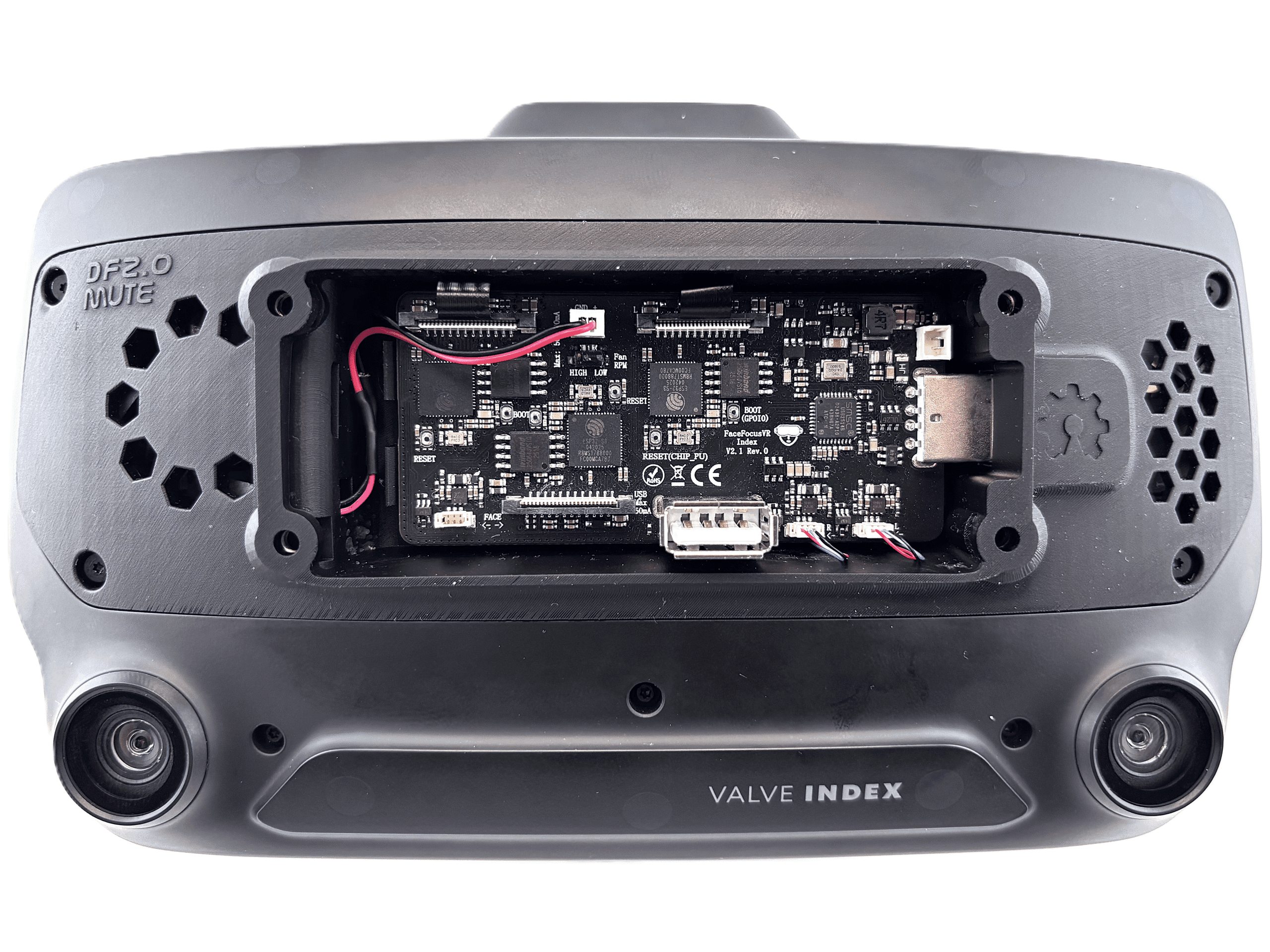
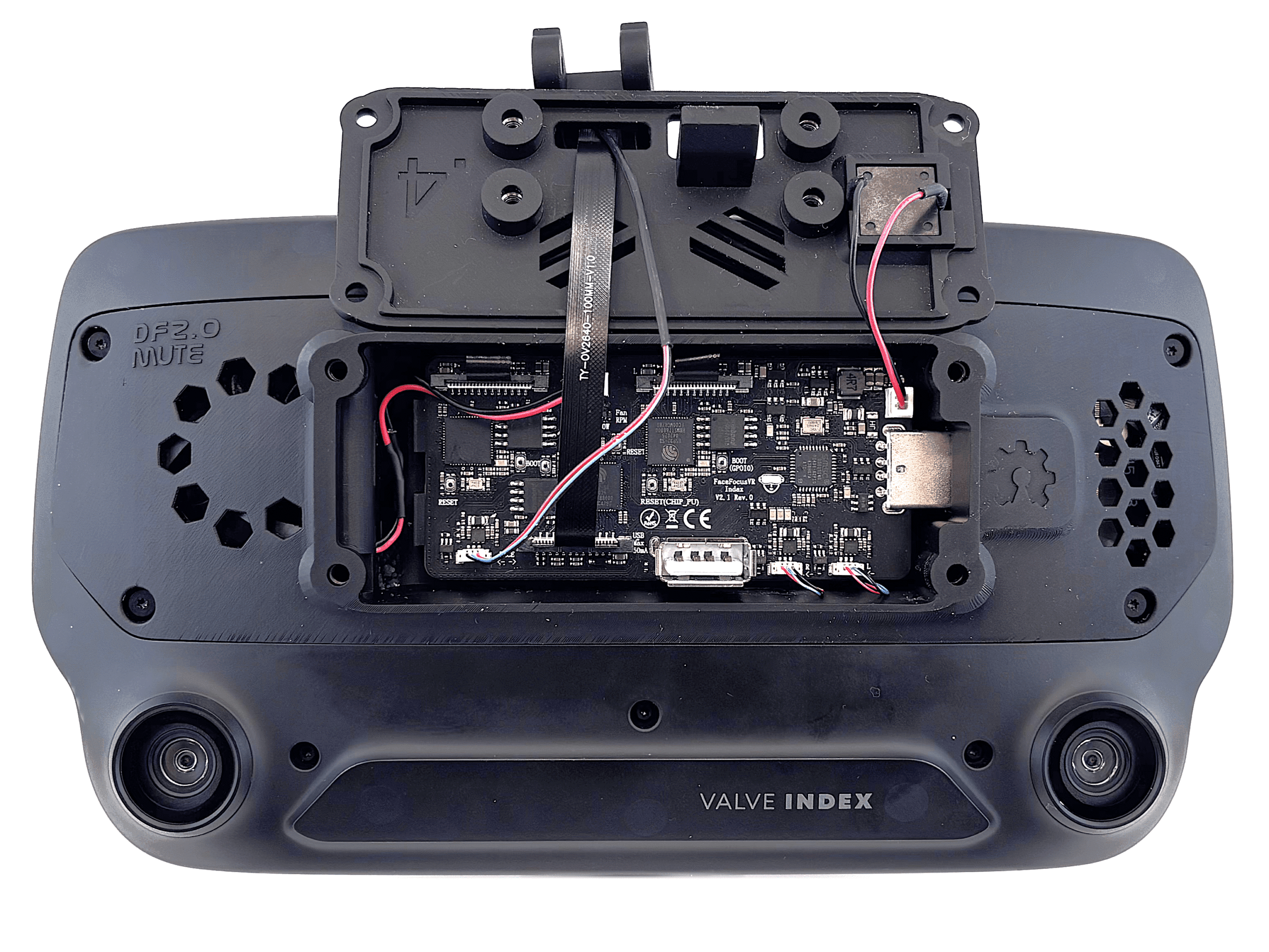
The FaceFocusVR board is the central piece of your kit. It connects all cameras, LEDs, and the fan. Before you start installing, take a moment to familiarize yourself with each connector and its purpose.
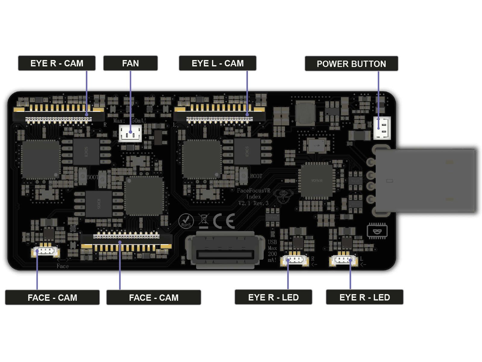
Camera Connectors
The three wide ribbon cable connectors are for the cameras: Eye Right and Eye Left at the top, and Face at the bottom. The eye cameras sit inside eye modules that mount around your headset lenses. The face camera sits in the face module.LED Connectors
The three small connectors along the bottom edge are for the infrared LEDs: Eye R and Eye L on the right, Face on the left. They ensure tracking works even in complete darkness.Fan / Power Button
The fan header at the top powers the cooling fan. The connector on the right side is where the power button connects.USB
The additional USB port on the front of the board can be used for extra accessories such as a Bluetooth dongle. However, since it is power-limited, I would not recommend using it.
Required Tools
- M3 Allen key (hex key)
- T5 Torx screwdriver
- (Self-holding) Tweezers optional but recommended
-
Optional: Replace VROptiker Prescription Lens Inserts
Only relevant if you use VROptiker prescription lens inserts and need to swap them into the new eye modules supplied with this kit. If you have the standard Index lenses, skip this step entirely and continue with Preparation.
 Opens on YouTube in a new tab ↗
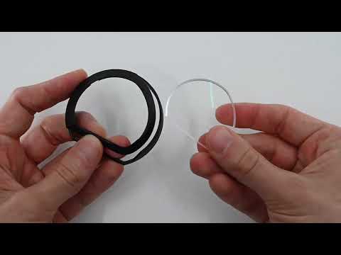
Part 1: Remove the existing lens insertsRemove your current prescription inserts from the holder. The video to your left shows the procedure.
-
 1 / 2
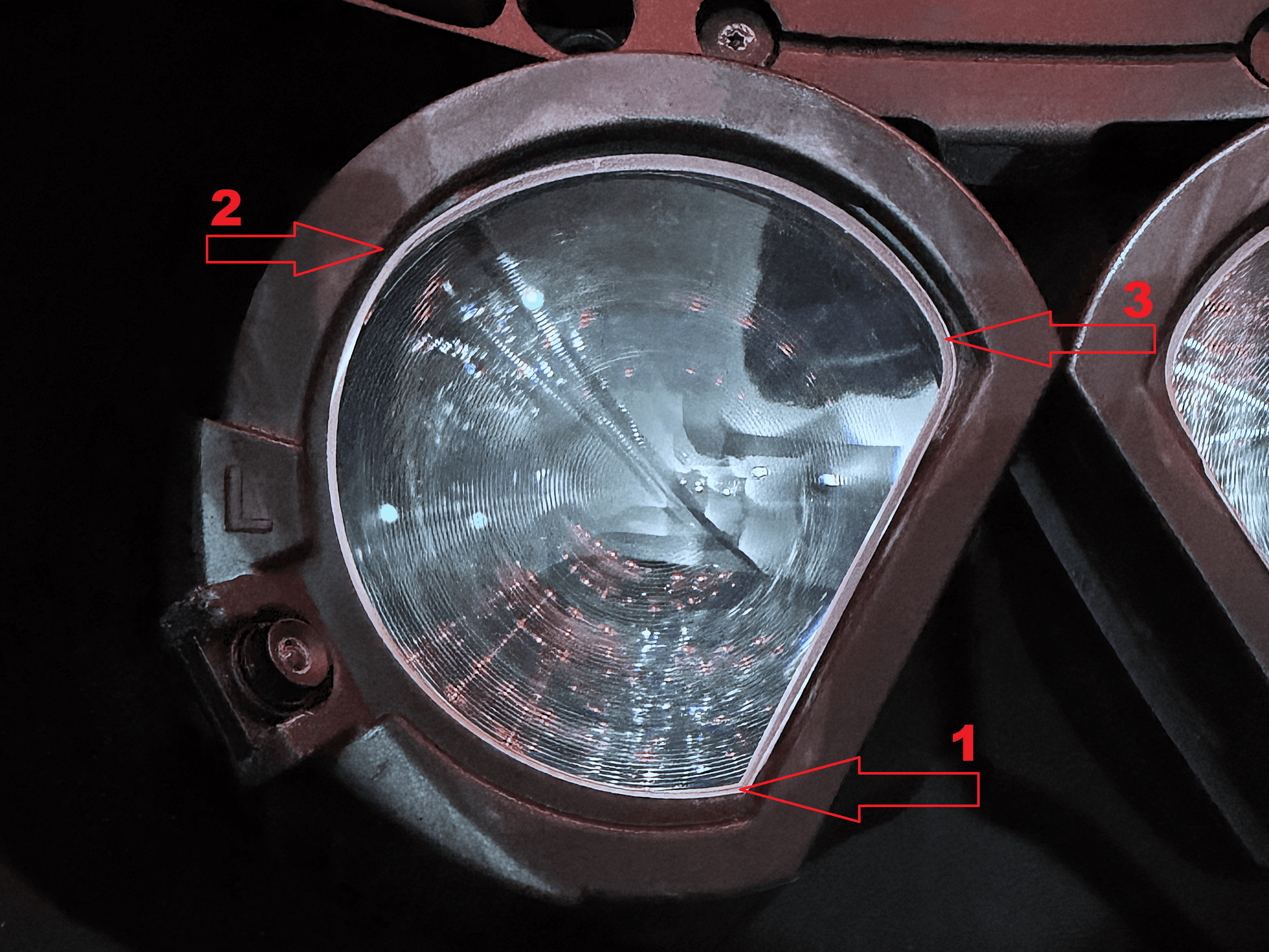
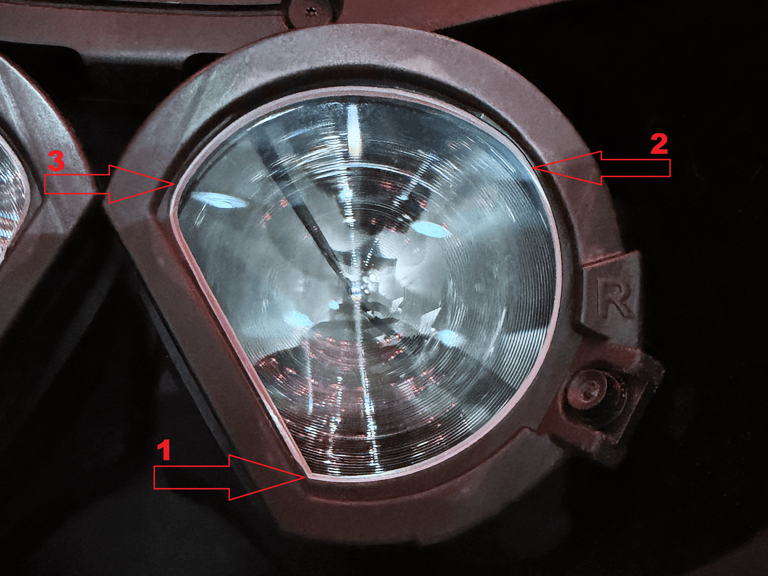
1 / 2Part 2: Install the lenses into the new eye modulesThe eye modules don't need to be installed in the headset for this step. It's easiest to do this in your hands. Use the original holder as a reference for how each lens should be oriented and how the holder holds it in place. Then click the lens into the matching eye module following the press order shown in the images.
- 1. Place the lower (sharper) corner of the lens into the eye module first.
- 2. Press the outer edge of the lens into the eye module until you hear it click into place.Before pressing 3, check that the lens edge between 1 and 2 sits in the groove, as shown in the images. You may need to hold the lens between two fingers (top and bottom) and nudge it into place.
- 3. Press the top of the lens into the eye module until you hear it click into place.
Once installed, gently push against the back of each lens to set it into its final position and confirm it stays in place.
Do not mix up the left (L) and right (R) lenses, and stick exactly to the press order (1 → 2 → 3) shown in the images. Pressing in the wrong order can permanently damage the eye module!
- 1
Preparation
Before you begin, prepare your headset by adjusting a few settings and removing detachable parts.
 Source: ifixit.com1 / 3
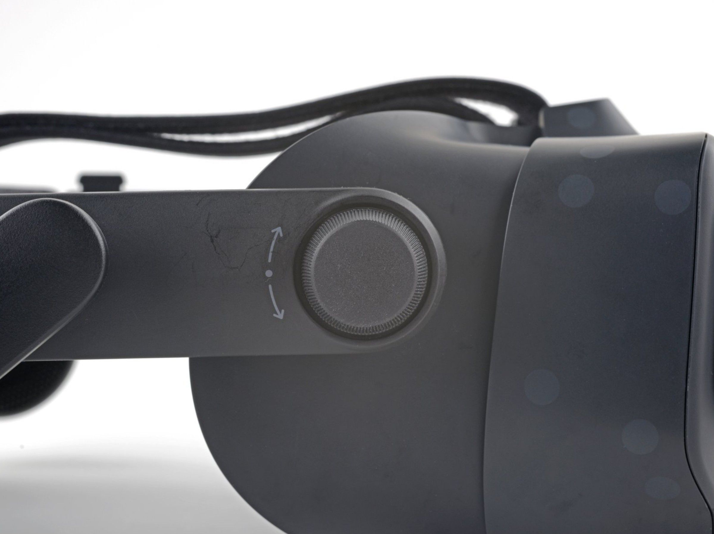
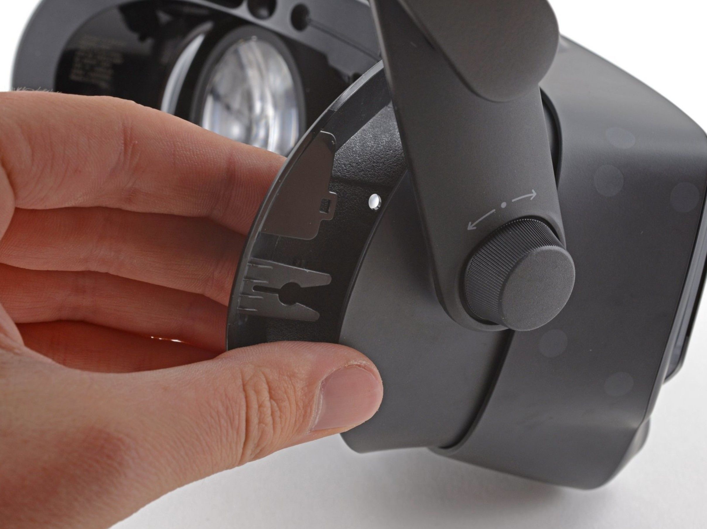
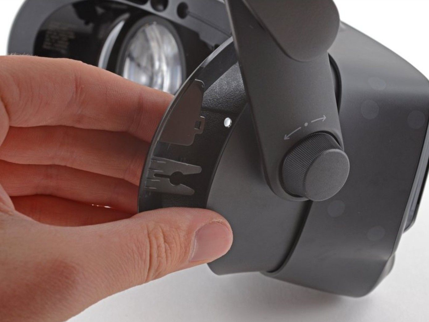
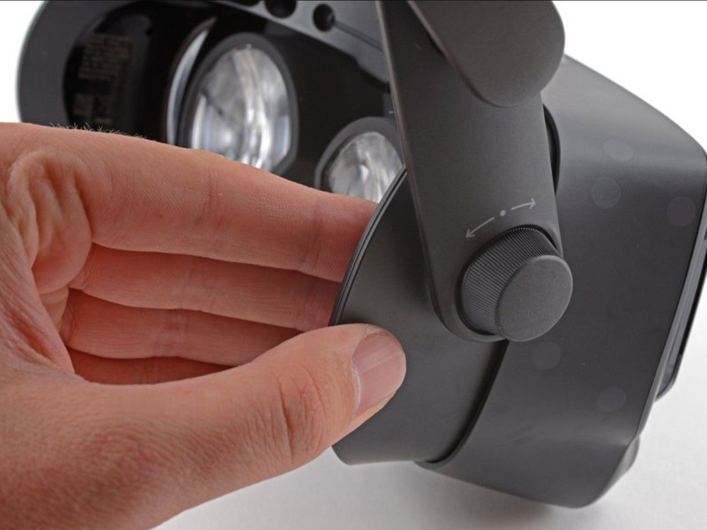
- Rotate the field-of-view adjustment knob clockwise until it is fully extended.
- Set the IPD to its minimum value (lenses fully inward).
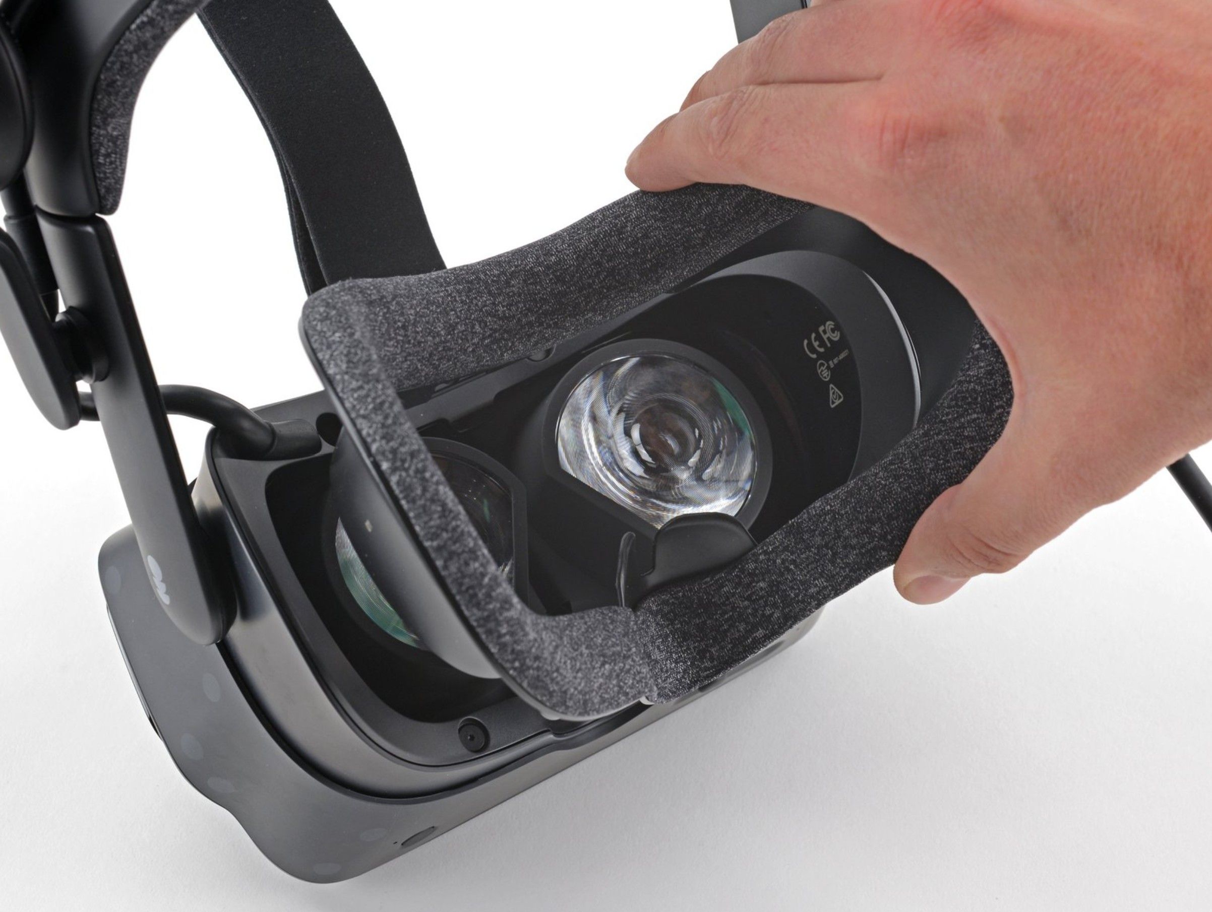
- Remove the magnetic face cushion.
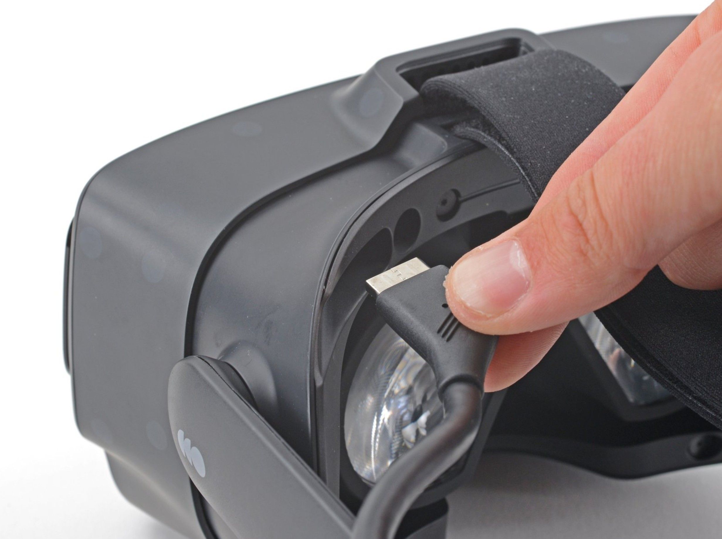
- Gently pull the tether cable straight out of the headset (only the cable itself; there's no need to remove the cable clips from the head strap).
- 2
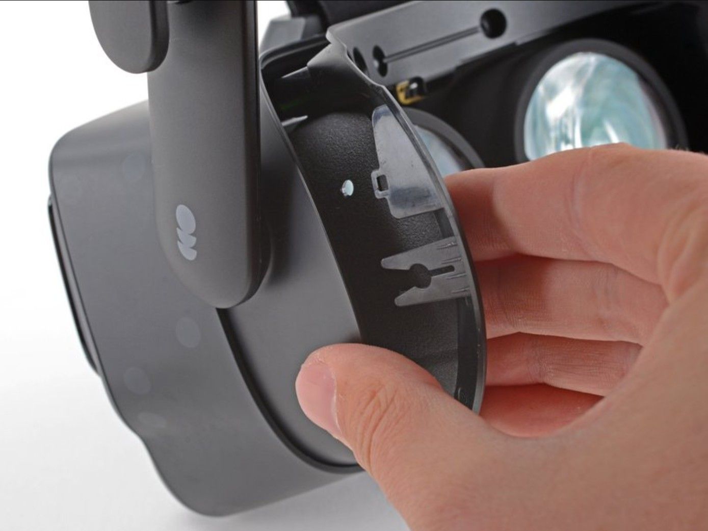
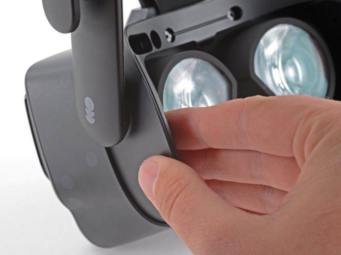
Remove the Face Gasket Bezel
The face gasket bezel needs to come off so you can access the internal components.


 Source: ifixit.com1 / 6
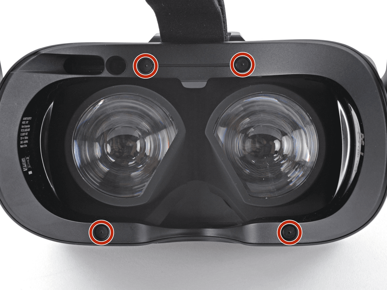
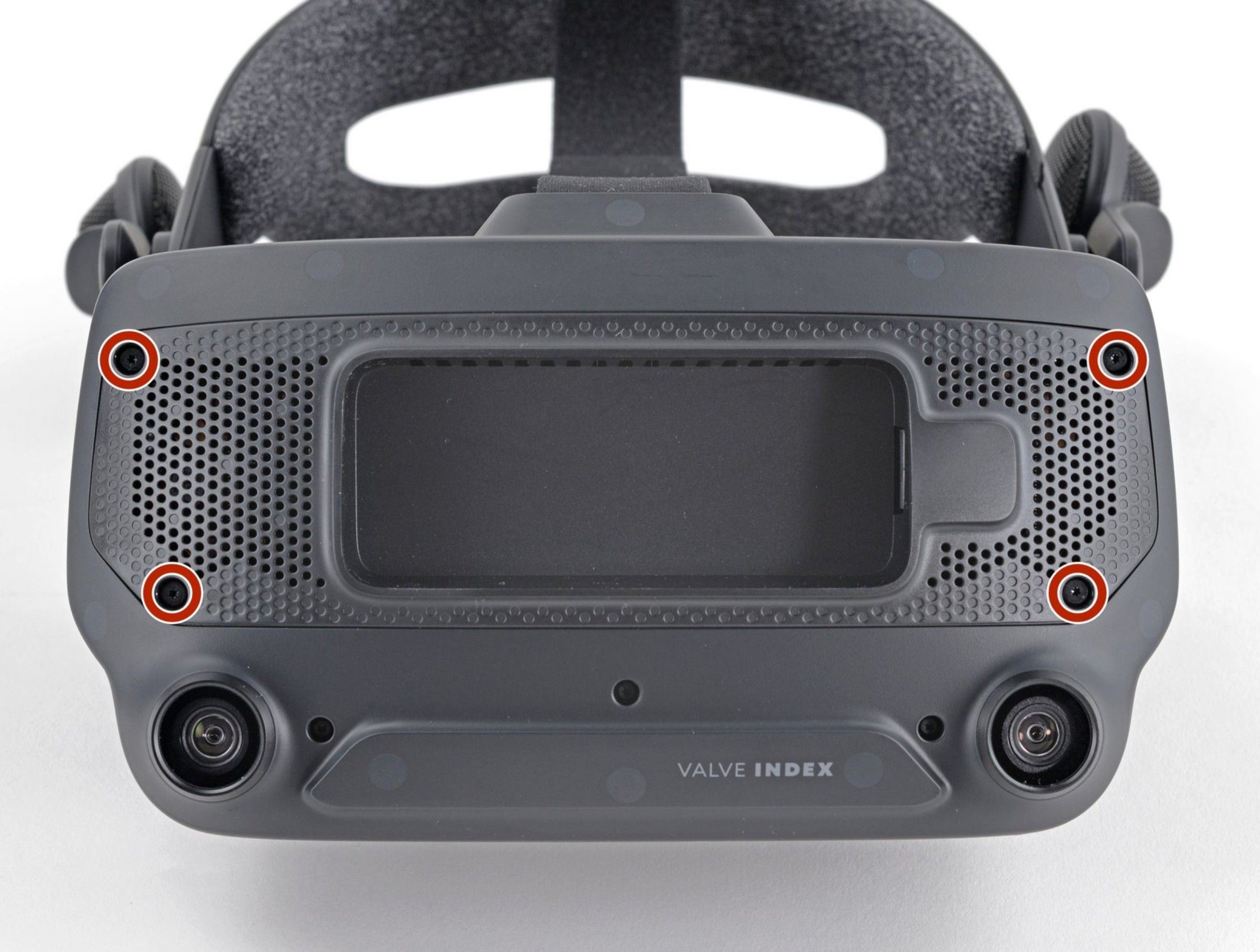
- Use a T5 Torx screwdriver to remove the four 6 mm screws securing the faceplate frame to the headset.
- Grab the left edge of the face gasket bezel with your hand and slide it off of the headset.
- Repeat the previous step for the right side of the face gasket bezel.
- Remove the face gasket bezel.
Do not try and pry the face gasket bezel off, or you will damage the headset.
- 3
Remove the Eye Tube Gasket
With the bezel removed, carefully detach the eye tube gasket using tweezers.
 Source: ifixit.com1 / 3
- Use a pair of tweezers to separate the left edge of the eye tube gasket from the headset by lifting the gasket carefully over the hooks on each side.
- Repeat the process for the right edge of the gasket.
- 4
Remove the Motherboard Cover
With the gasket removed, take off the front cover and motherboard cover to access the internals.
 Source: ifixit.com1 / 3
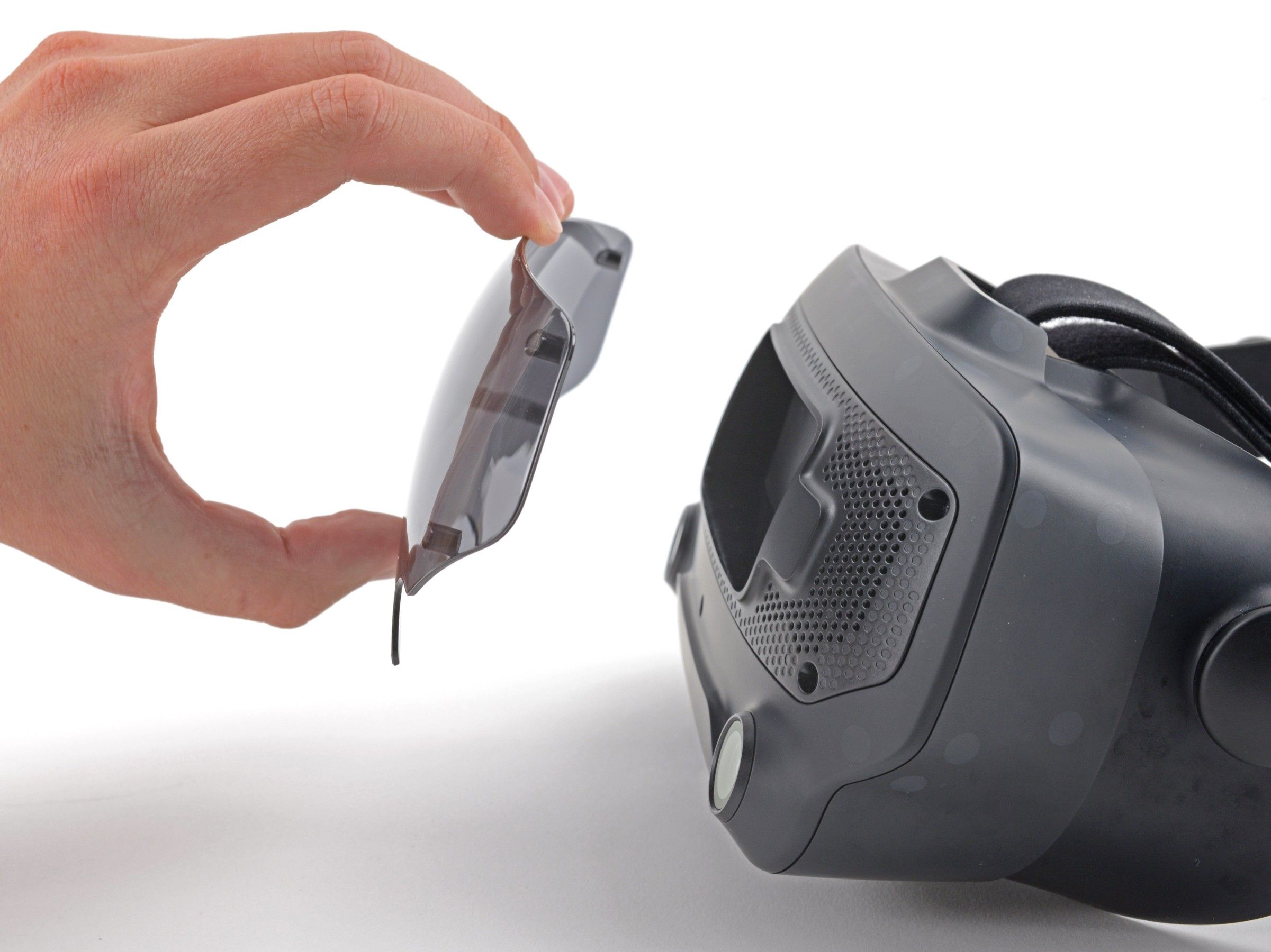
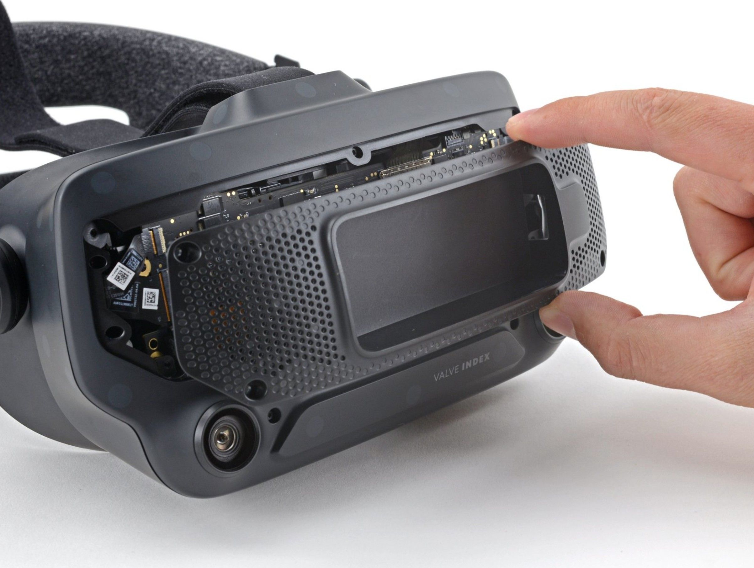
- Pull the front cover straight off of the front of the headset. It is held in place by four magnets.
- Use a T5 Torx screwdriver to remove the four 5.4 mm screws securing the motherboard cover to the headset.
- Remove the motherboard cover from the headset.
-
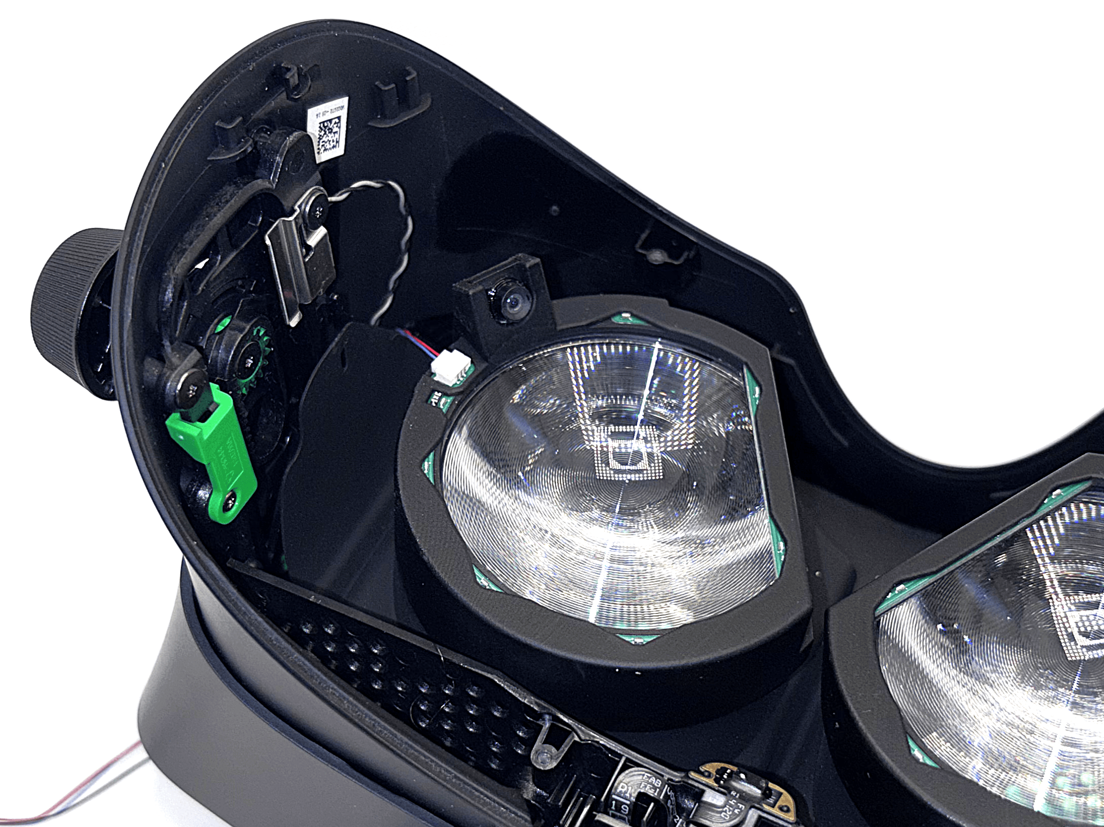
Goal for Steps 5, 6, 7 and 8
From this point onward, the process becomes more delicate because you are working with ribbon cables. Take your time!
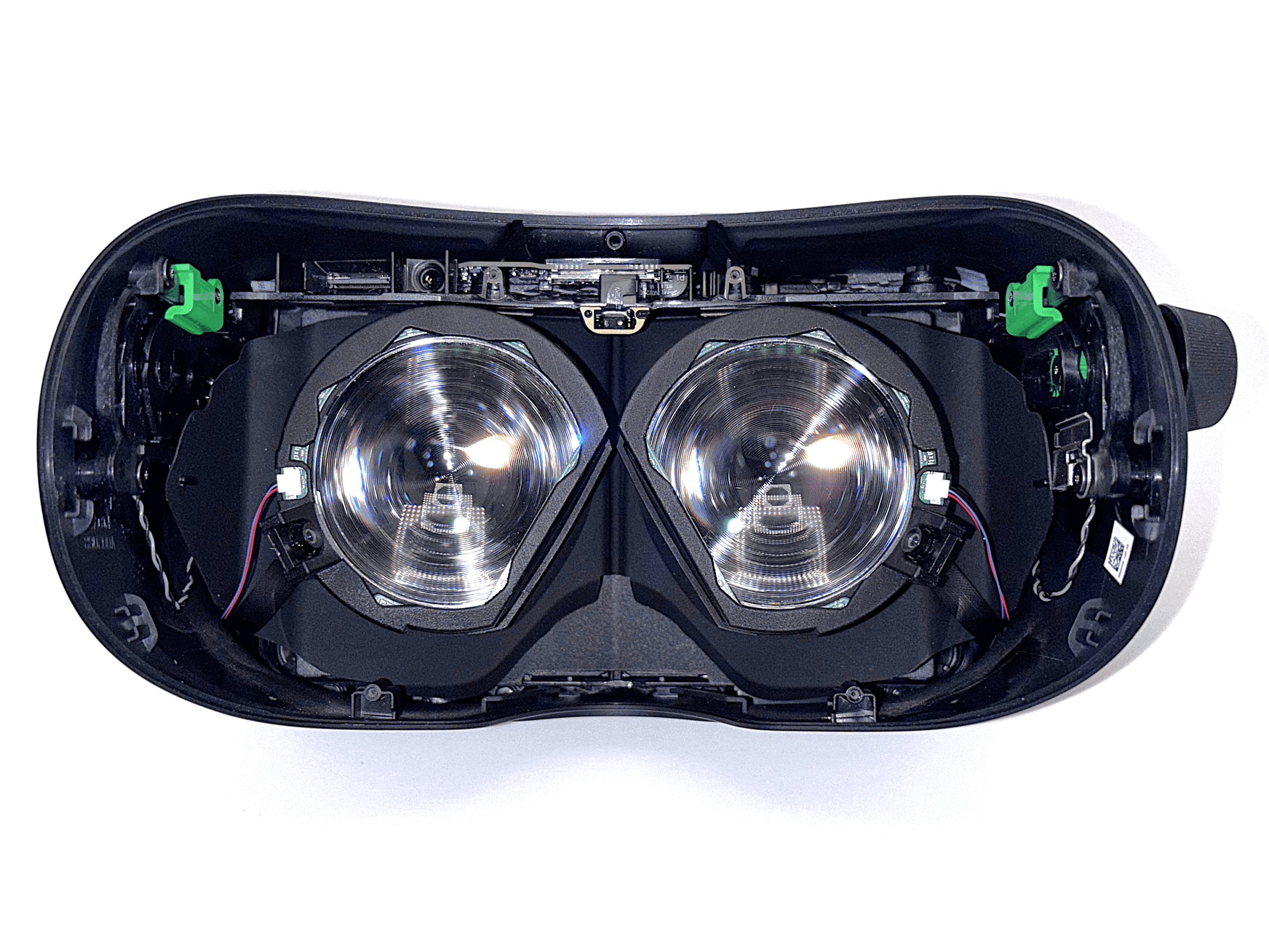
 1 / 4
1 / 4In the next four steps, you will install the two eye modules used for eye tracking. Each eye module contains a circuit board with LEDs for eye illumination and a camera.
Since it's often easier to work toward a visible goal, the images show what your setup should look like after completing steps 5, 6, 7, and 8.
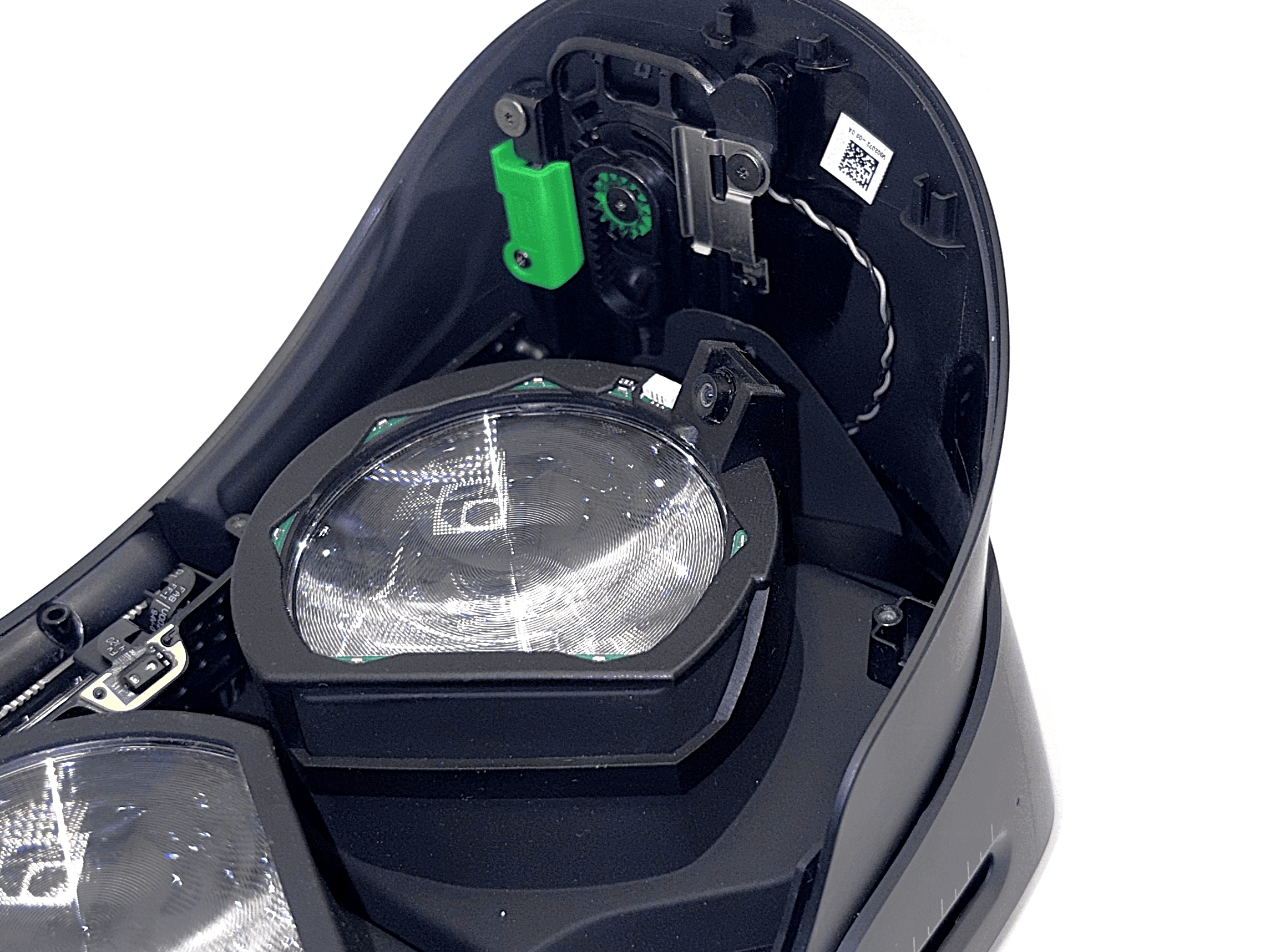
In step 5, you will route the ribbon cable for the left side through the headset. In step 6, you will do the same for the right side. Steps 7 and 8 will then connect the LED modules.
In the end, there should be four cables coming out of the front of your Index, positioned exactly as shown.
On newer revisions of the kit, the LEDs and connector are recessed into the eye module, with the LED cable pre-attached.
- 5
Routing the Left Ribbon Cable
Guide the left ribbon cable through the headset so it exits on the front side.
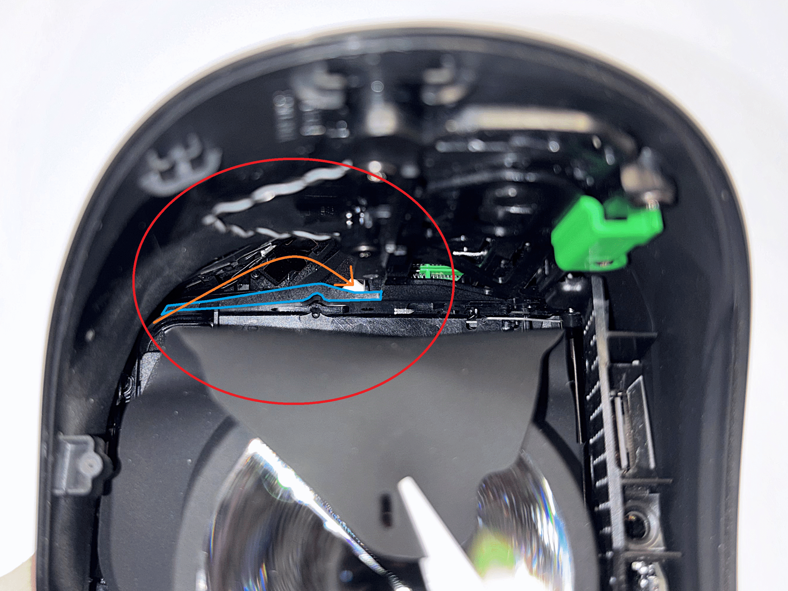
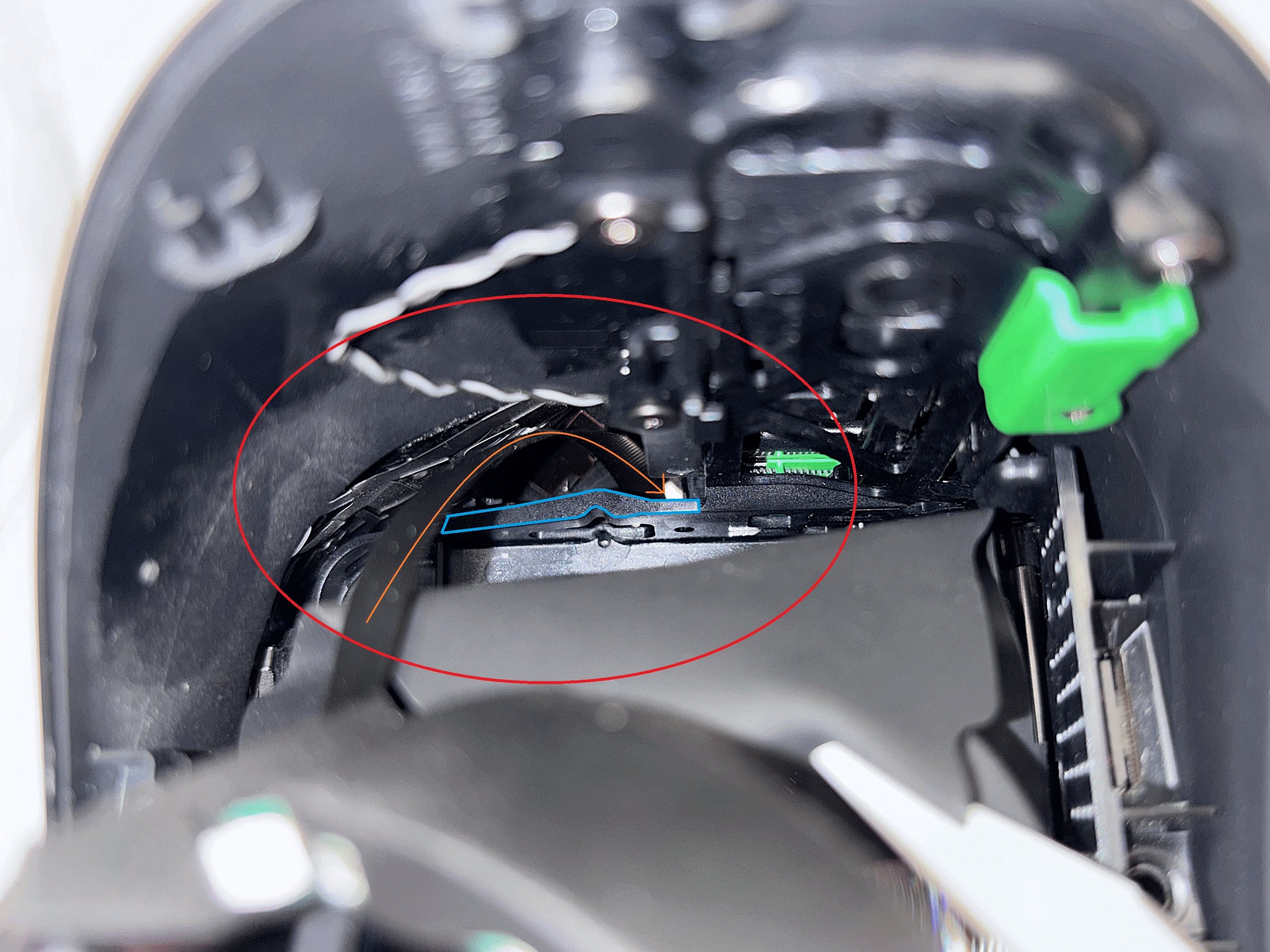
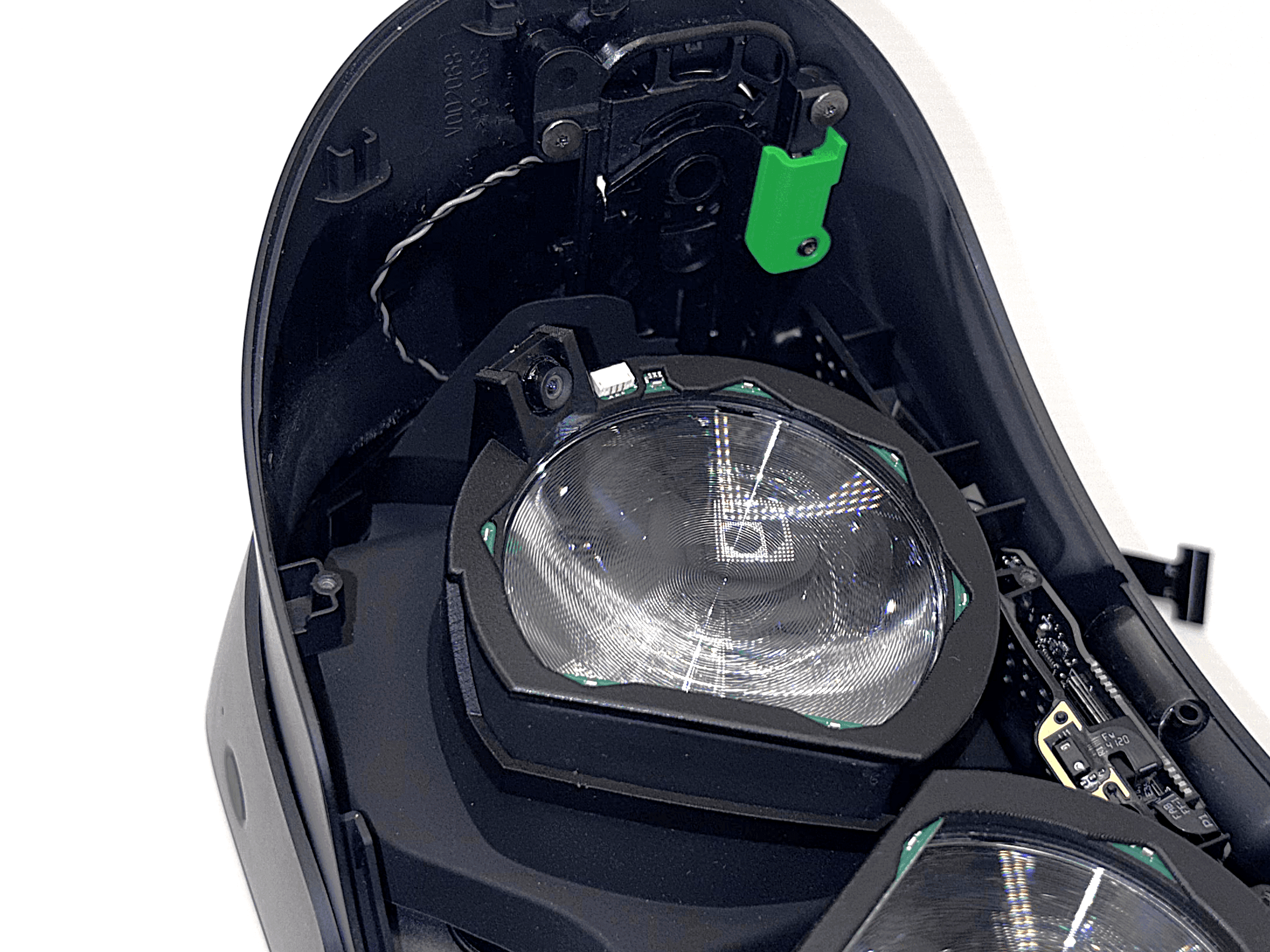
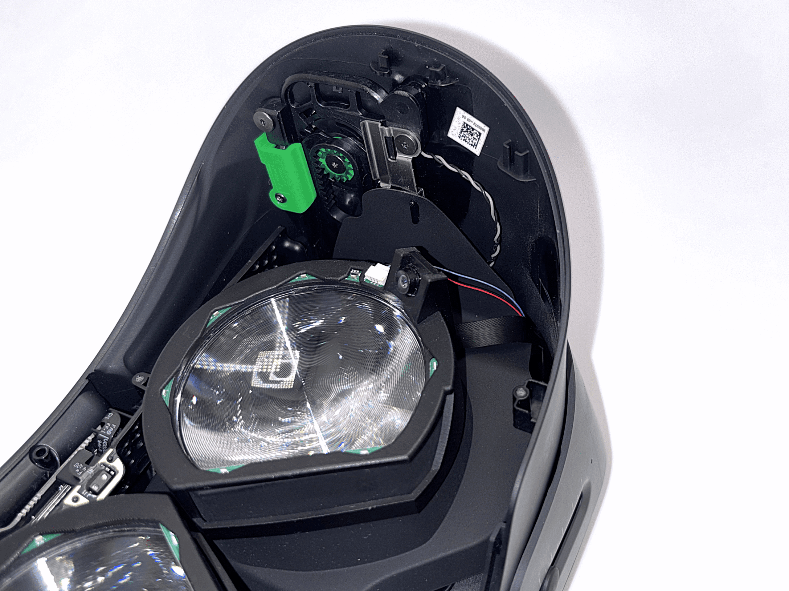
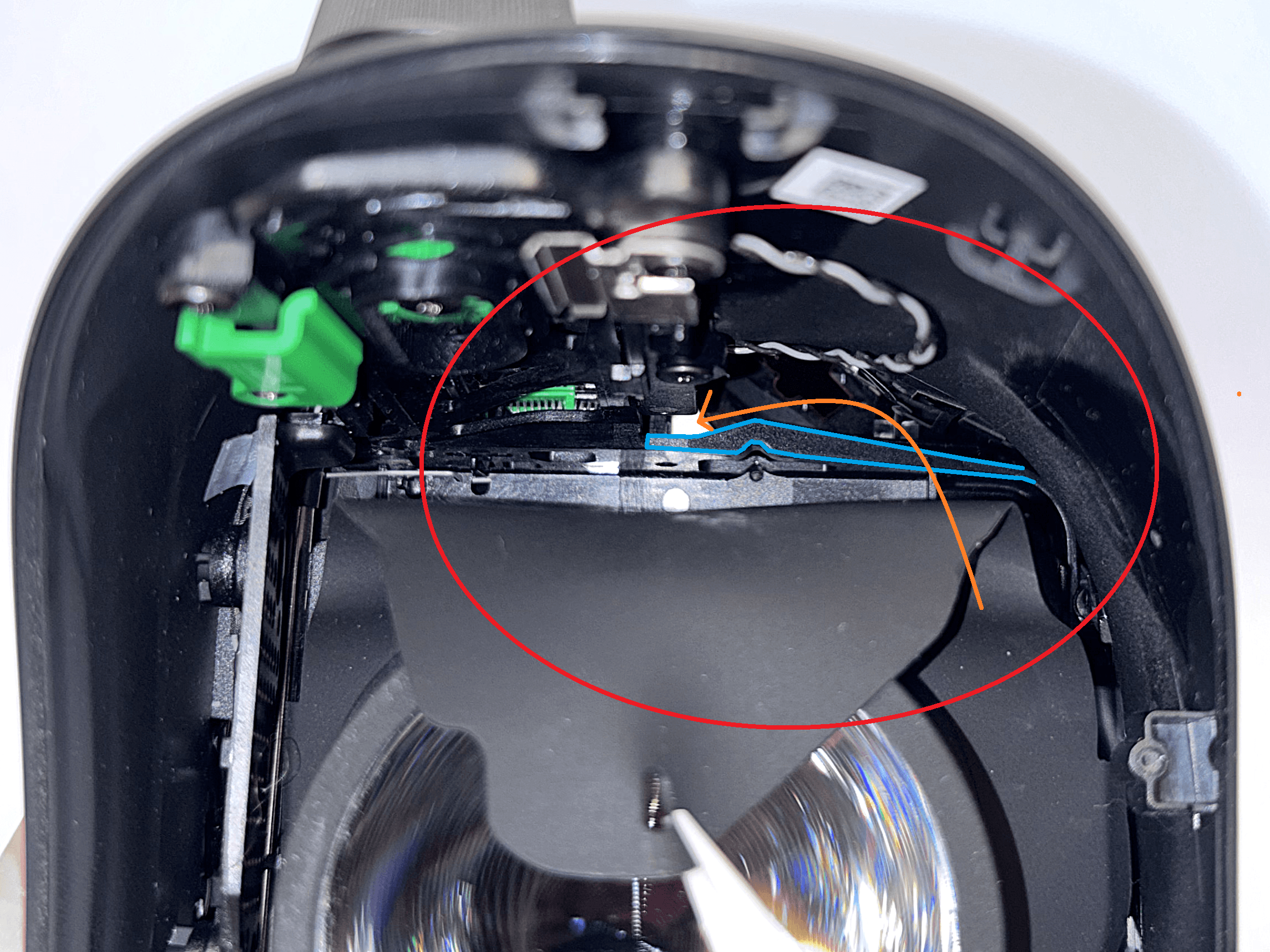
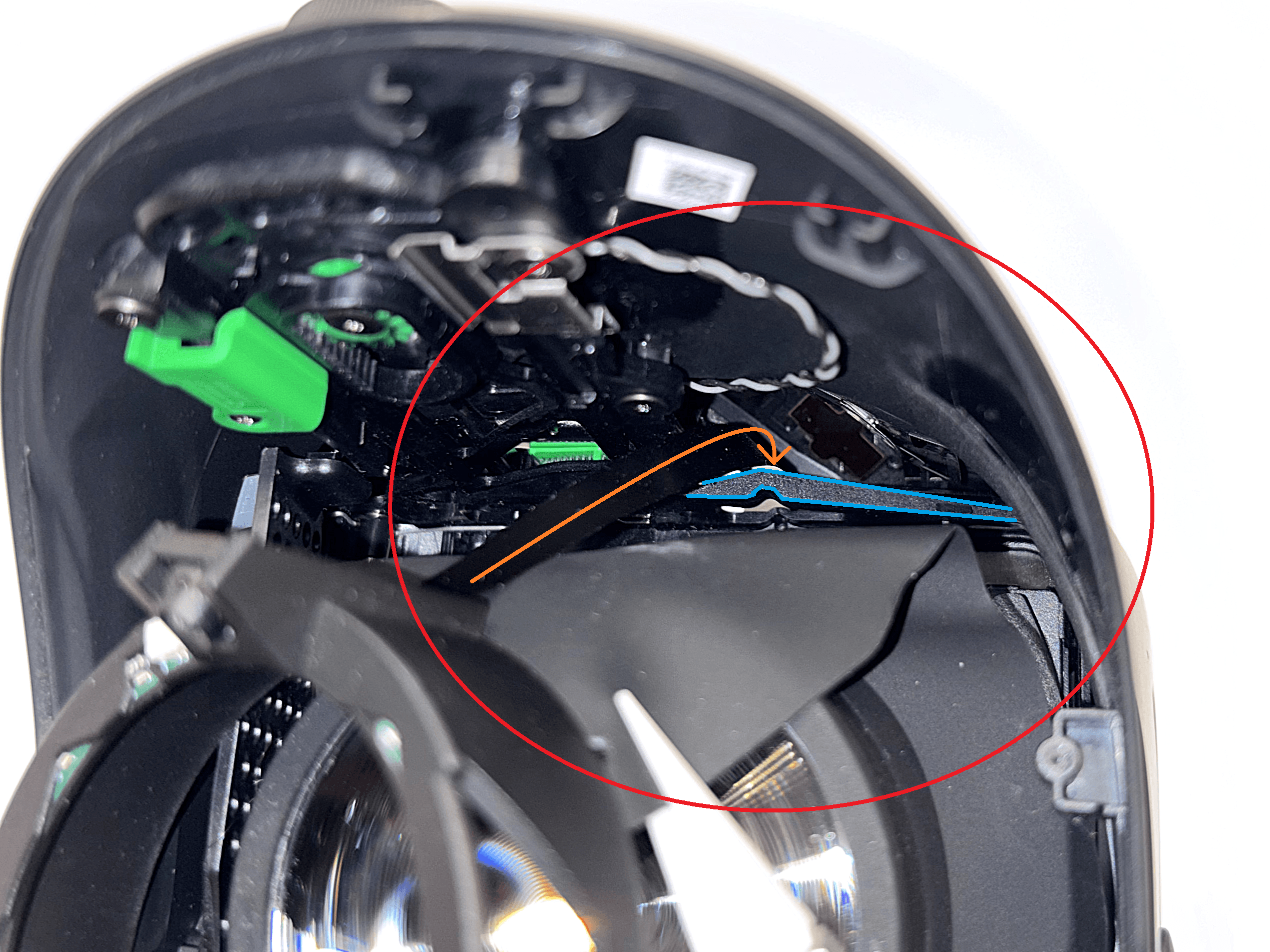
 1 / 4
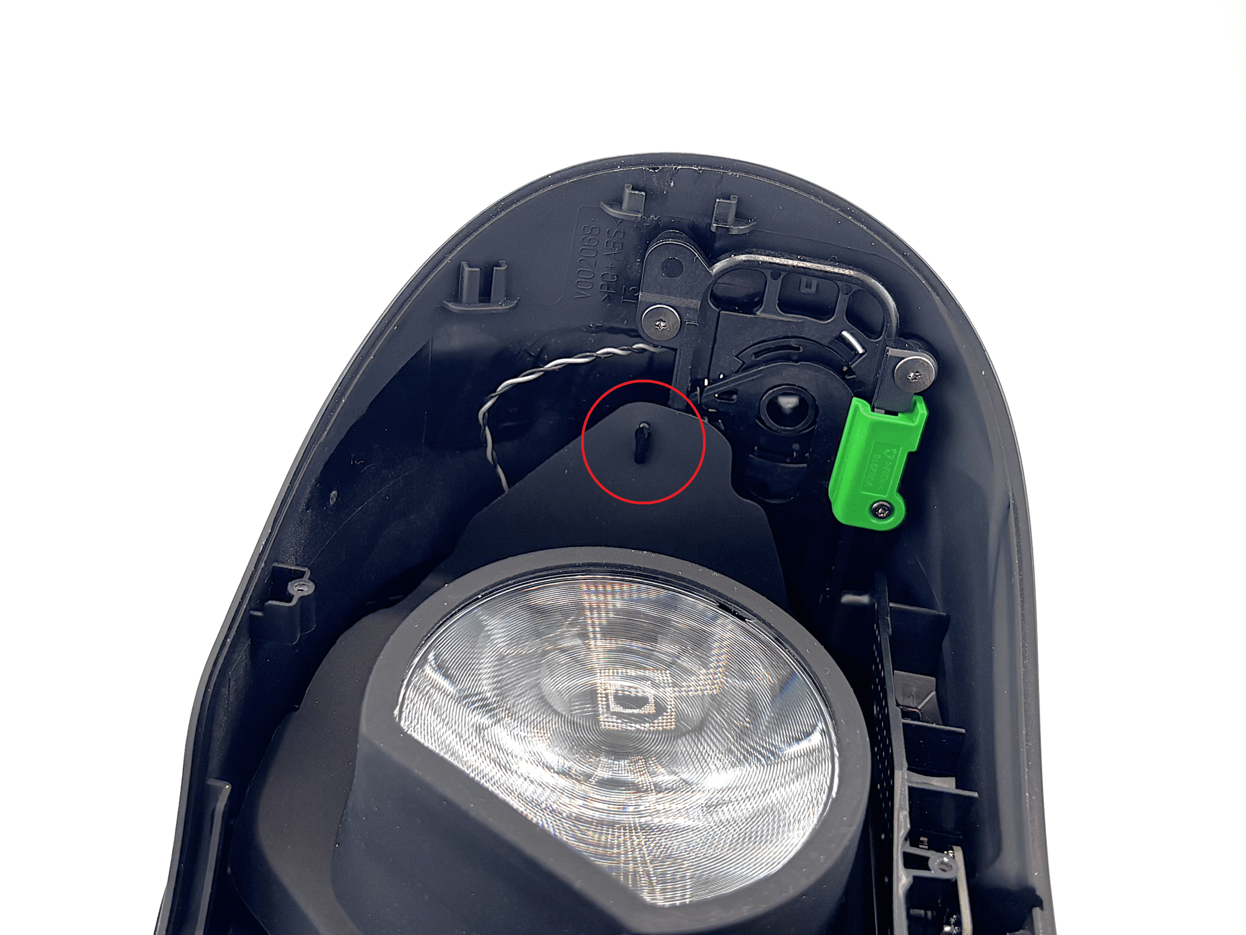
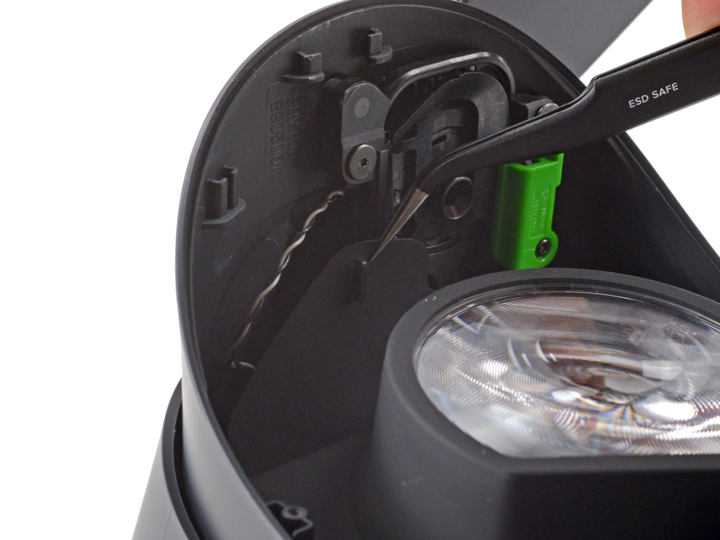
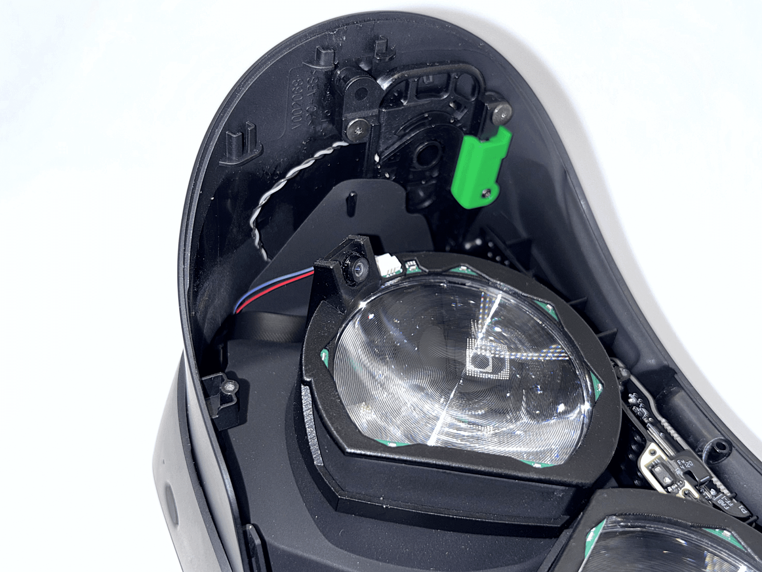
1 / 4The ribbon cable should pass behind the blue-marked plastic piece and exit through the bright hole, following the orange arrow shown in the reference image.
If you have difficulty guiding the cable through the hole or seeing it, place a light source in front of the headset to clearly see where the cable should exit.
In the last image, you can see where the ribbon cable should exit. With enough light and some patience, it's quite easy to guide the ribbon cable through the hole.
Once the cable has reached the other side, gently press the eye module onto the lens to keep it in place.
- 6
Routing the Right Ribbon Cable
Now repeat step 5 for the right side.
 1 / 4
1 / 4The ribbon cable should again pass behind the blue-marked plastic piece and exit through the bright hole, following the orange arrow shown in the reference image.
In the last image, you can see where the ribbon cable should exit.
Once the cable has reached the other side, gently press the eye module onto the lens to hold it in place.
- 7
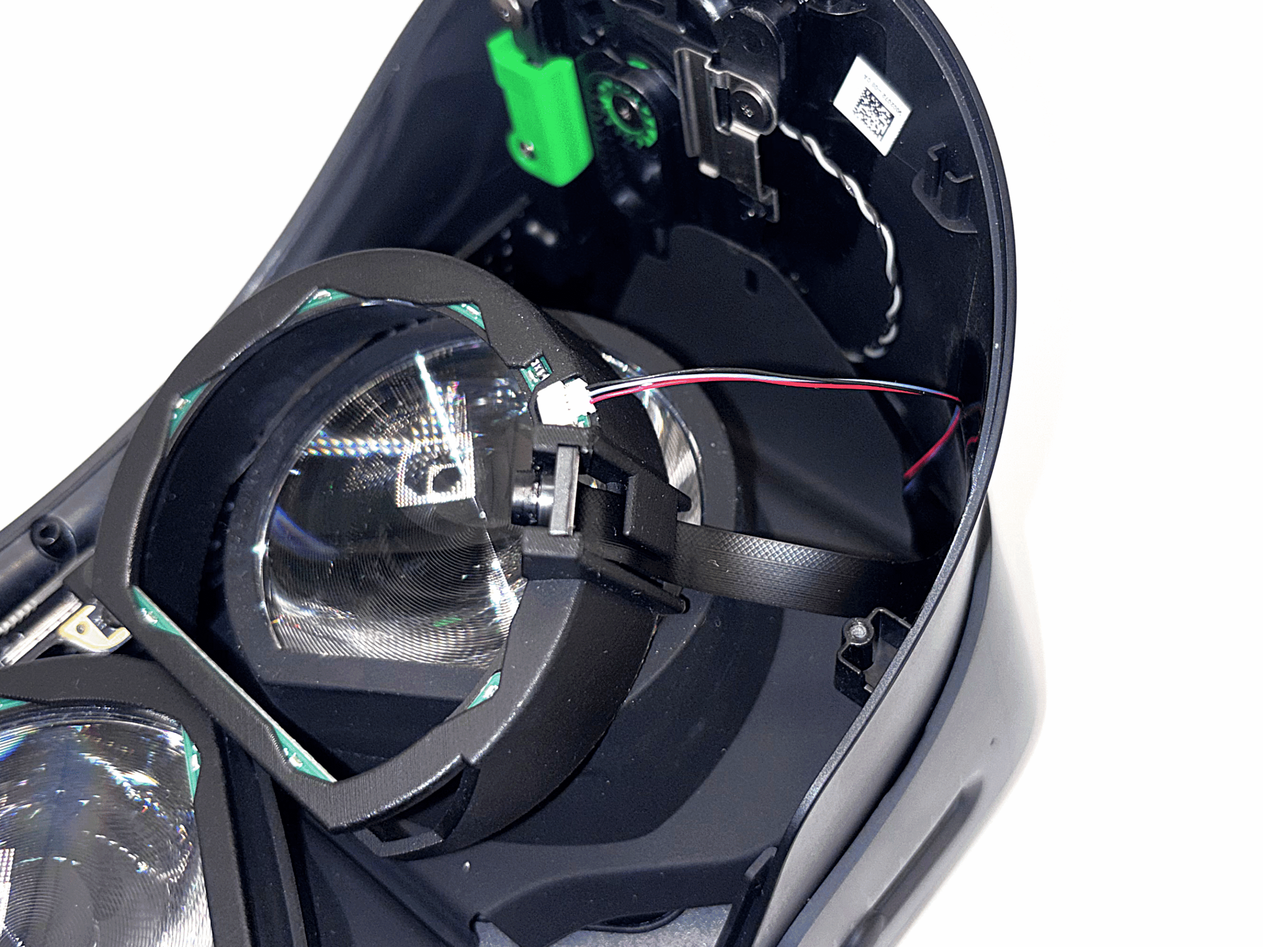
Routing the Left LED Cable
Route the flexible LED cable on the left side through the same path used in step 5.
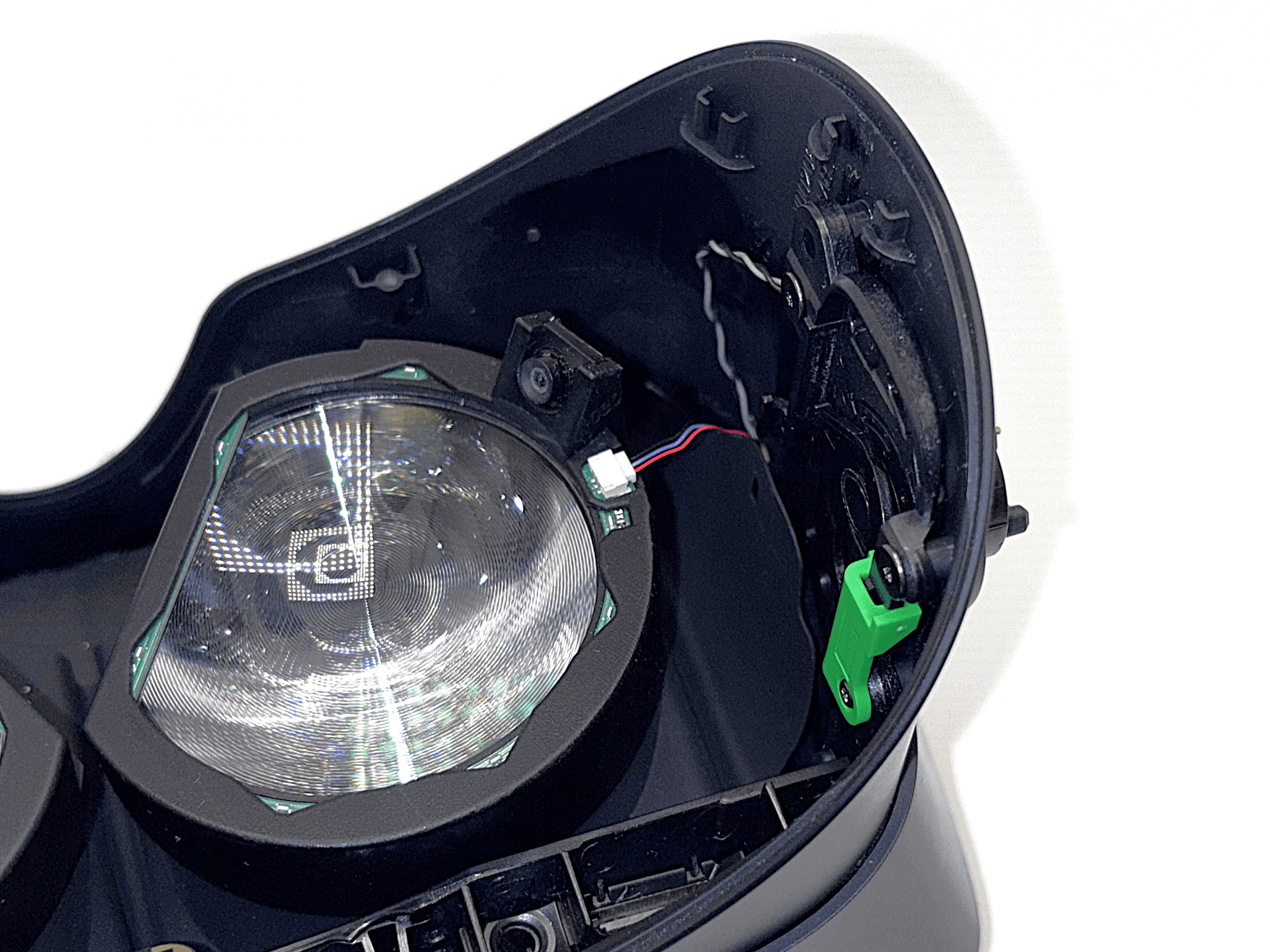 1 / 3
1 / 3After routing the two ribbon cables for the cameras, route the left flexible LED cable along the same path as shown in step 5.
You may need to slightly lift the eye module off the lens to guide the cable through. Be careful not to let the camera ribbon cable slip out while doing so.
After connecting the cable to the eye module, press the eye module back onto the lens and gently pull any excess cable out from the front.
- 8
Routing the Right LED Cable
Route the flexible LED cable on the right side through the same path used in step 6.
 1 / 3
1 / 3Now repeat step 7 for the right side. Route the right flexible LED cable along the same path as shown in step 6.
Again, you may need to slightly lift the eye module off the lens to guide the cable through. Be careful not to let the camera ribbon cable slip out while doing so.
After connecting the cable to the eye module, press the eye module back onto the lens and gently pull any excess cable out from the front.
- 9
Reattach the Eye Tube Gasket
With all cables routed, reattach the eye tube gasket to the headset.
 Source: ifixit.com1 / 3
- Use a pair of tweezers to place the left edge of the eye tube gasket onto the small hooks on the headset.
- Repeat the process for the right side of the gasket.
- 10
Reattach the Face Gasket Bezel
With all cables in place, reattach the face gasket bezel to complete the hardware installation.
 Source: ifixit.com1 / 6
- Position both sides of the face gasket bezel and carefully slide it onto the headset.
- Use a T5 Torx screwdriver to fasten the four 6 mm screws, securing the bezel to the headset and reattach the magnetic face cushion.
Make sure the clips on the face gasket bezel are properly aligned with the headset before sliding it fully into place.
- 11
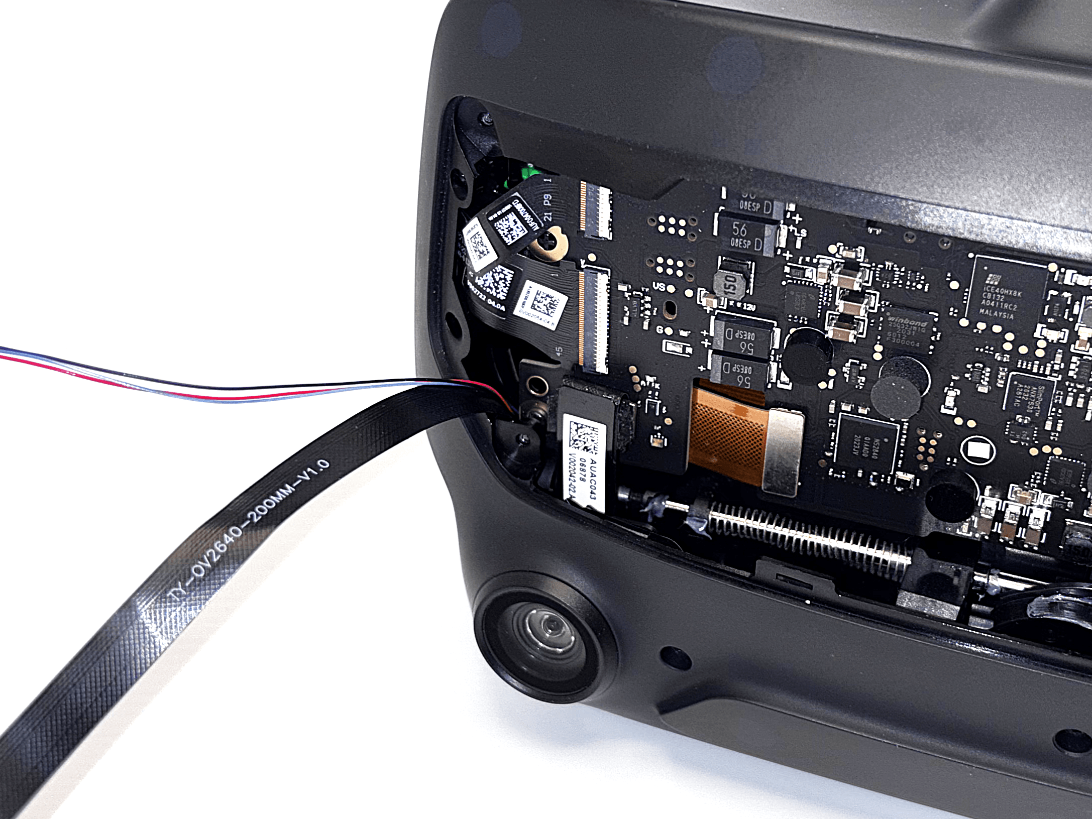
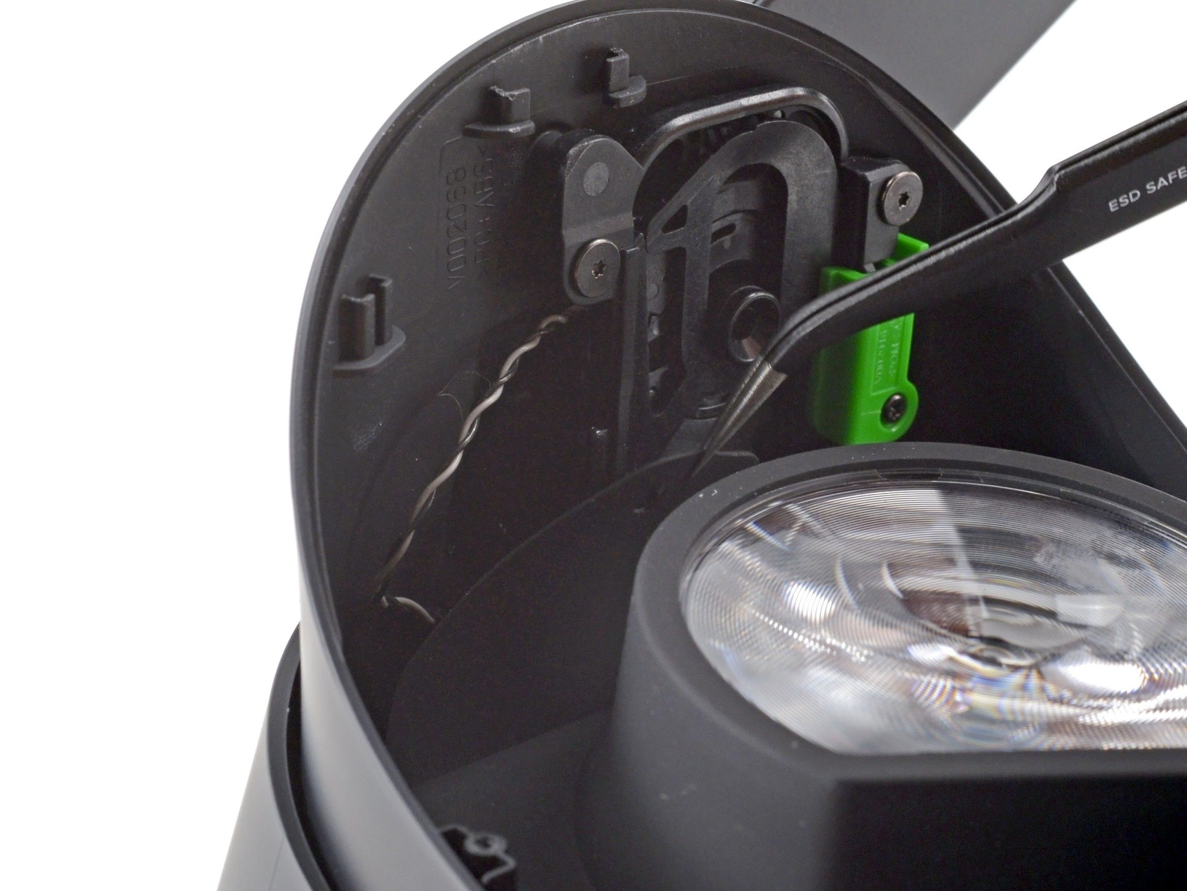
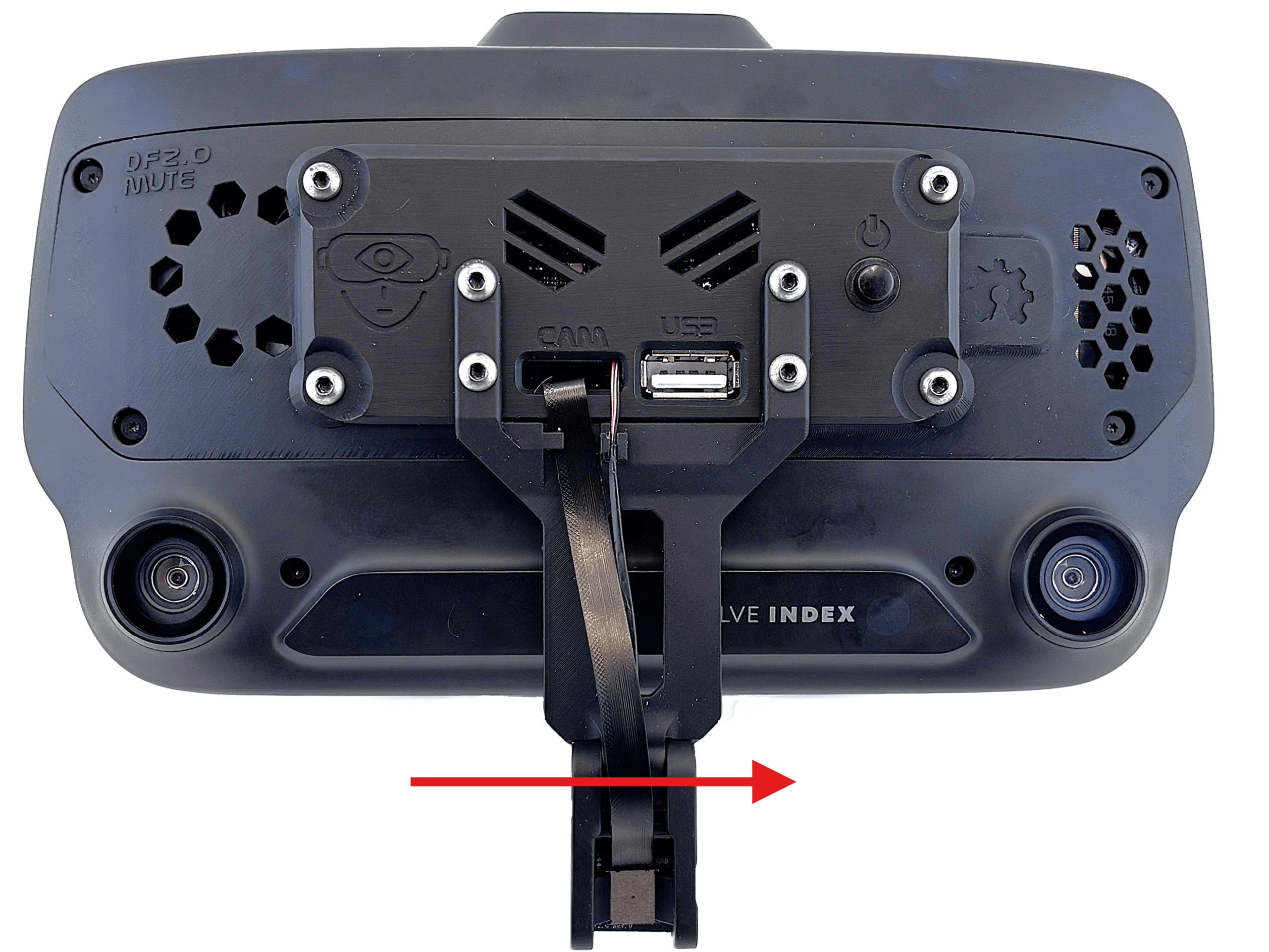
Cable Routing Preparation
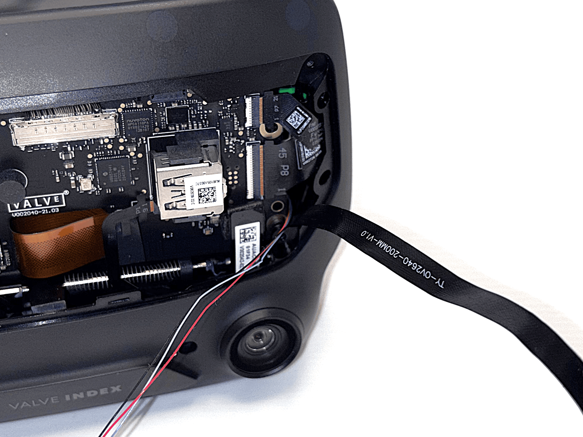
To prevent the left ribbon cable from getting caught in the fan, it needs to be routed through a specific gap.
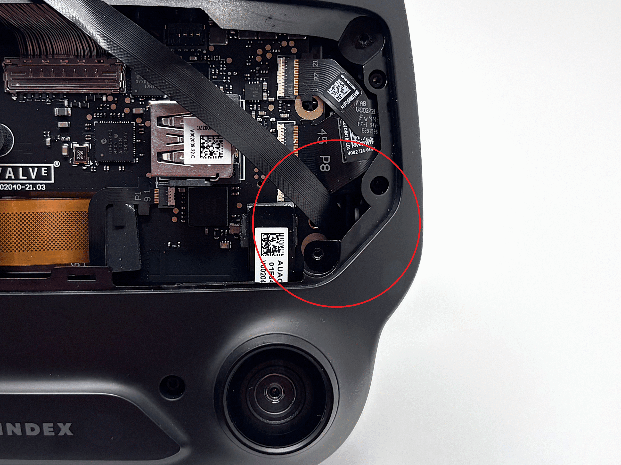
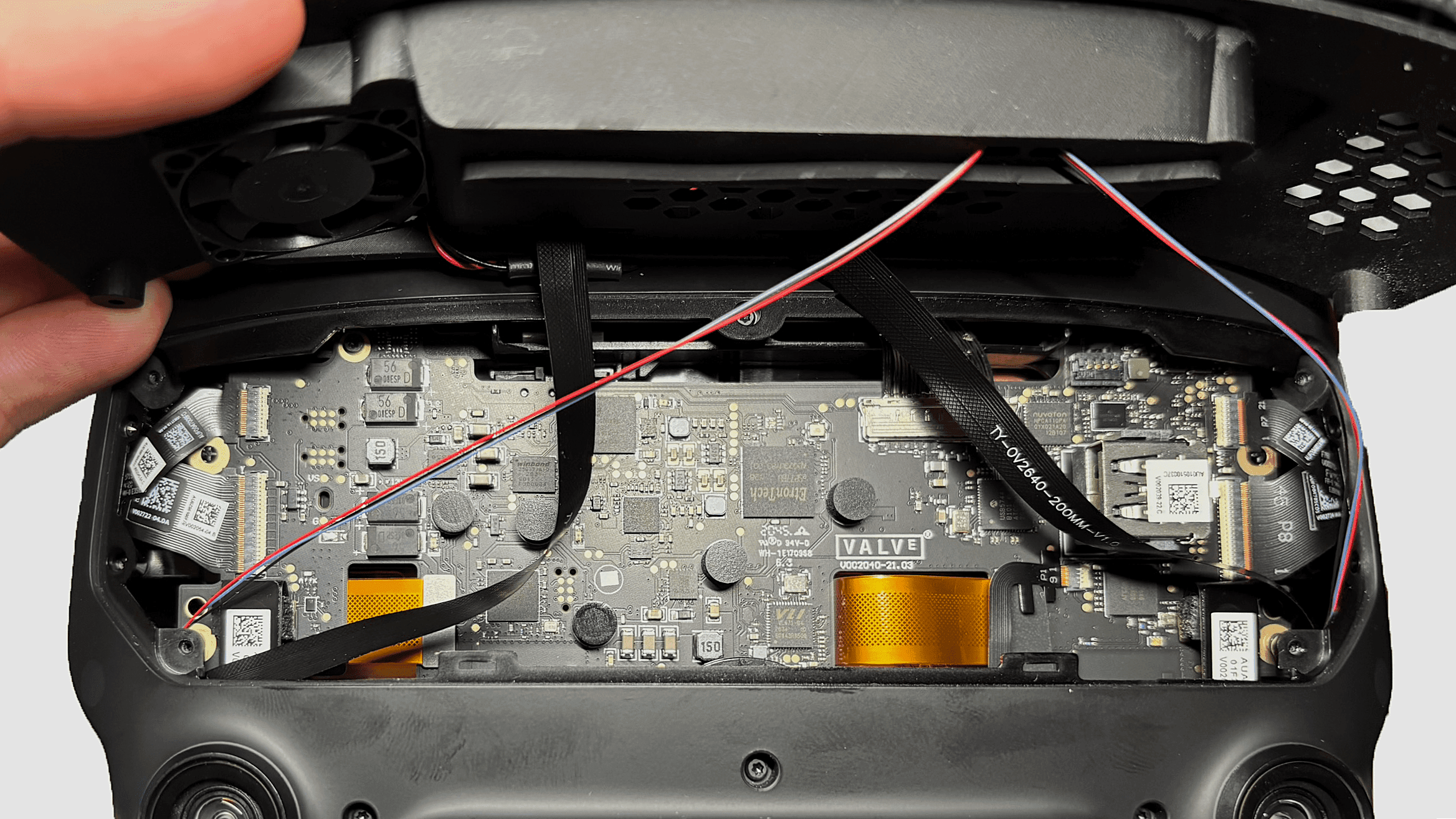
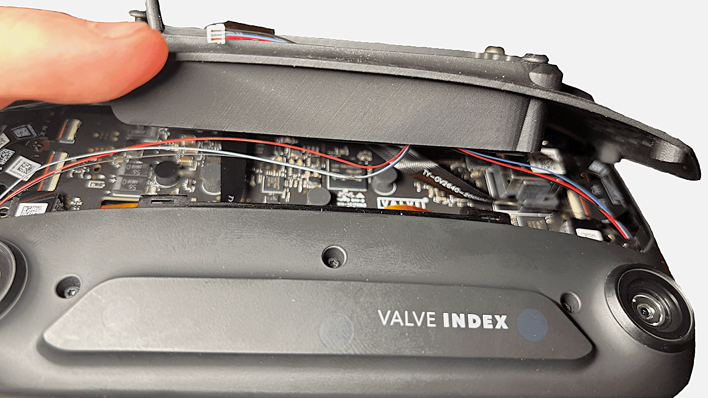
 1 / 4
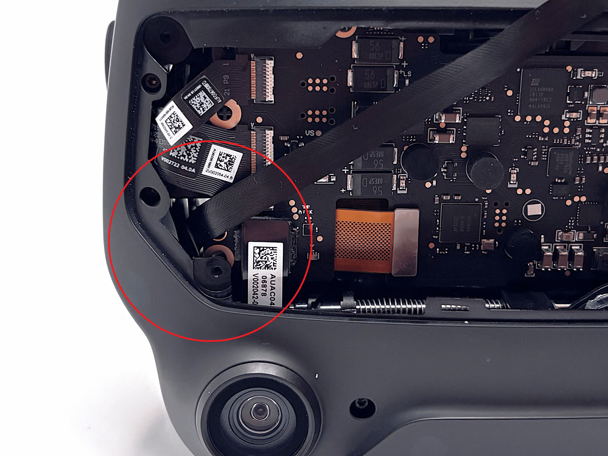
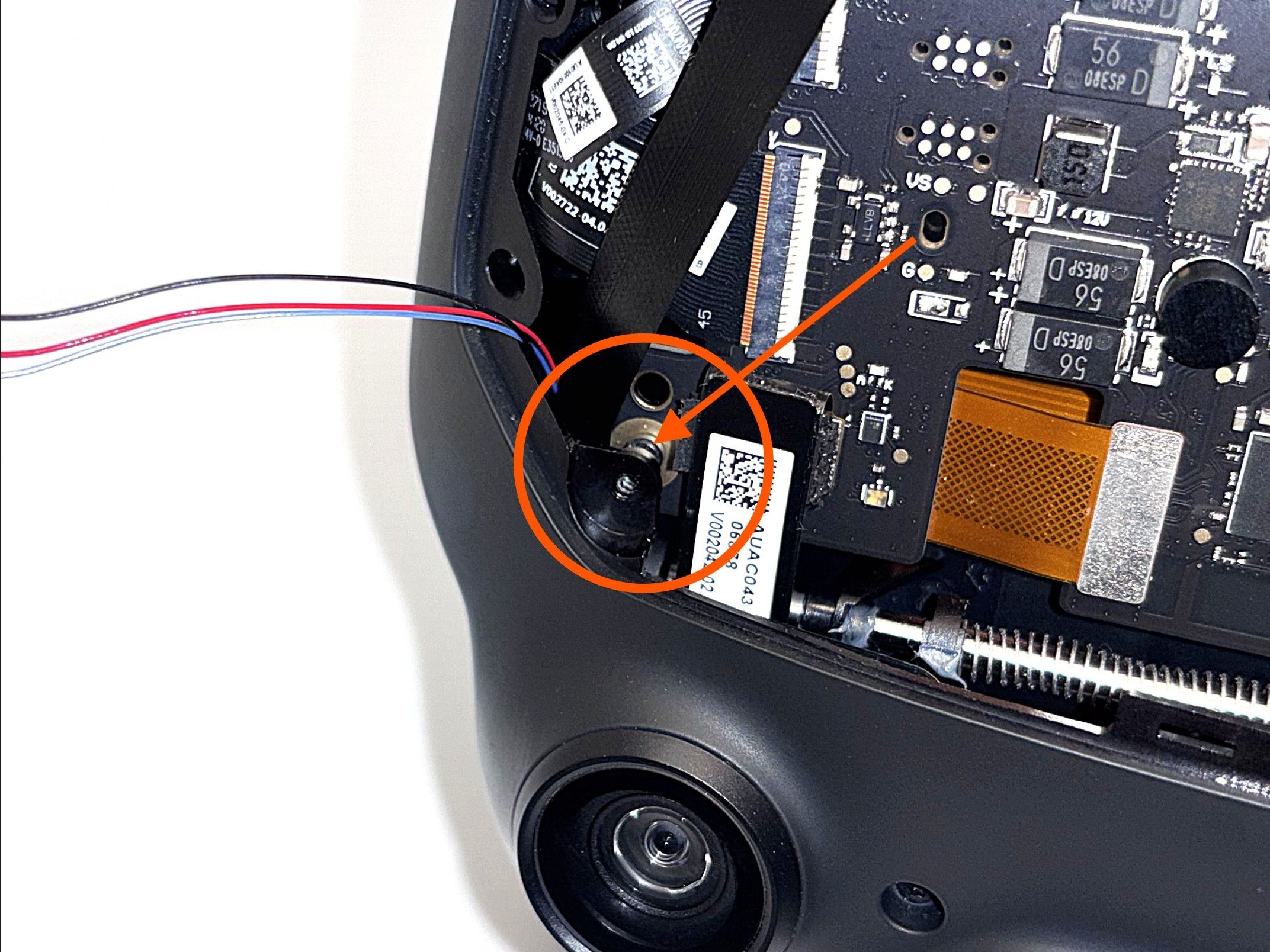
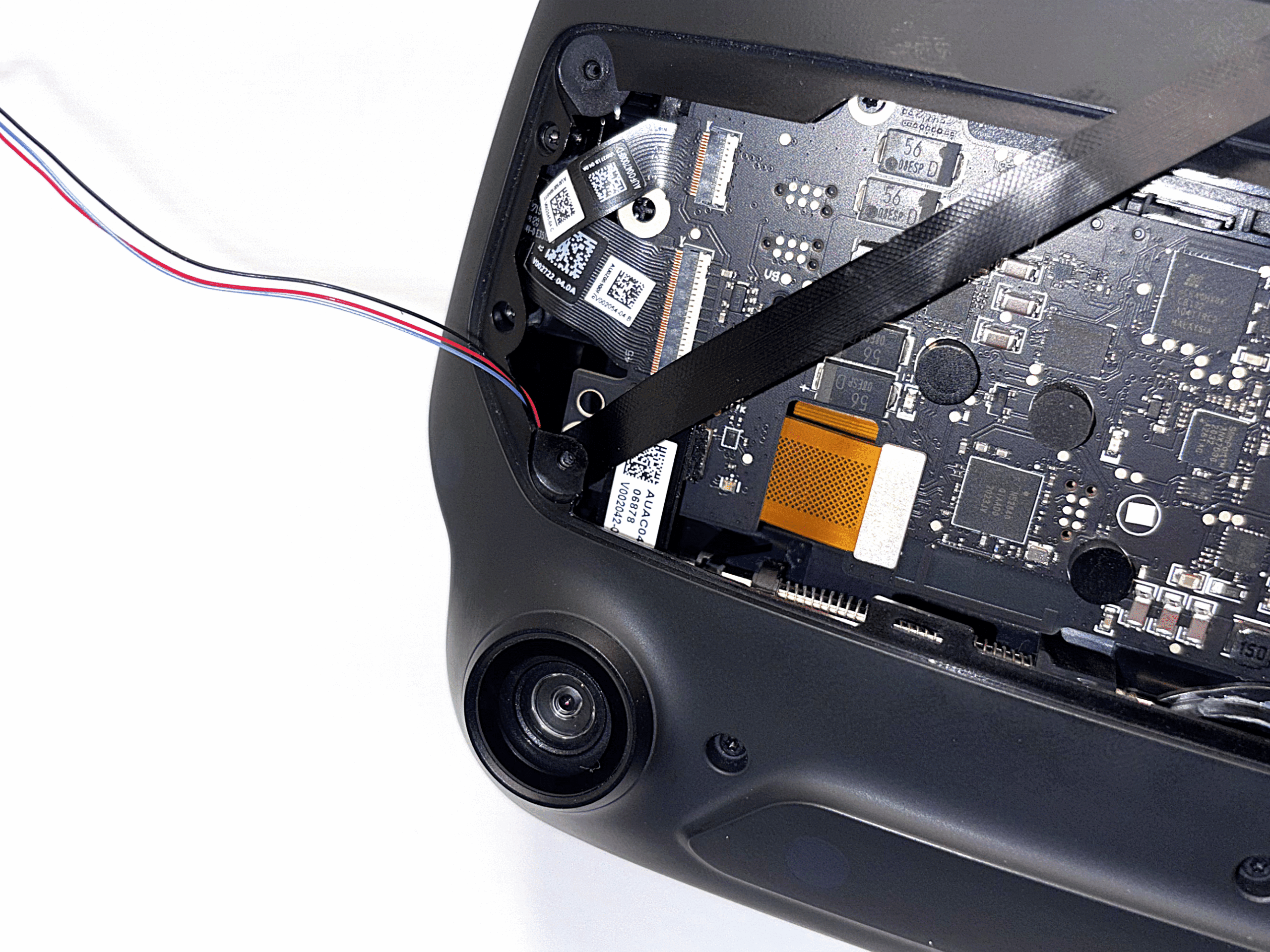
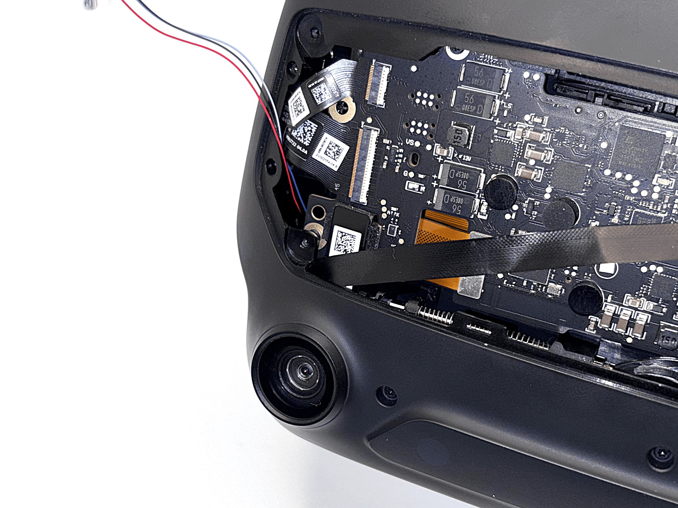
1 / 4- Make sure the field-of-view adjustment is still fully extended and that the IPD is set to the lowest setting (lenses fully inward).
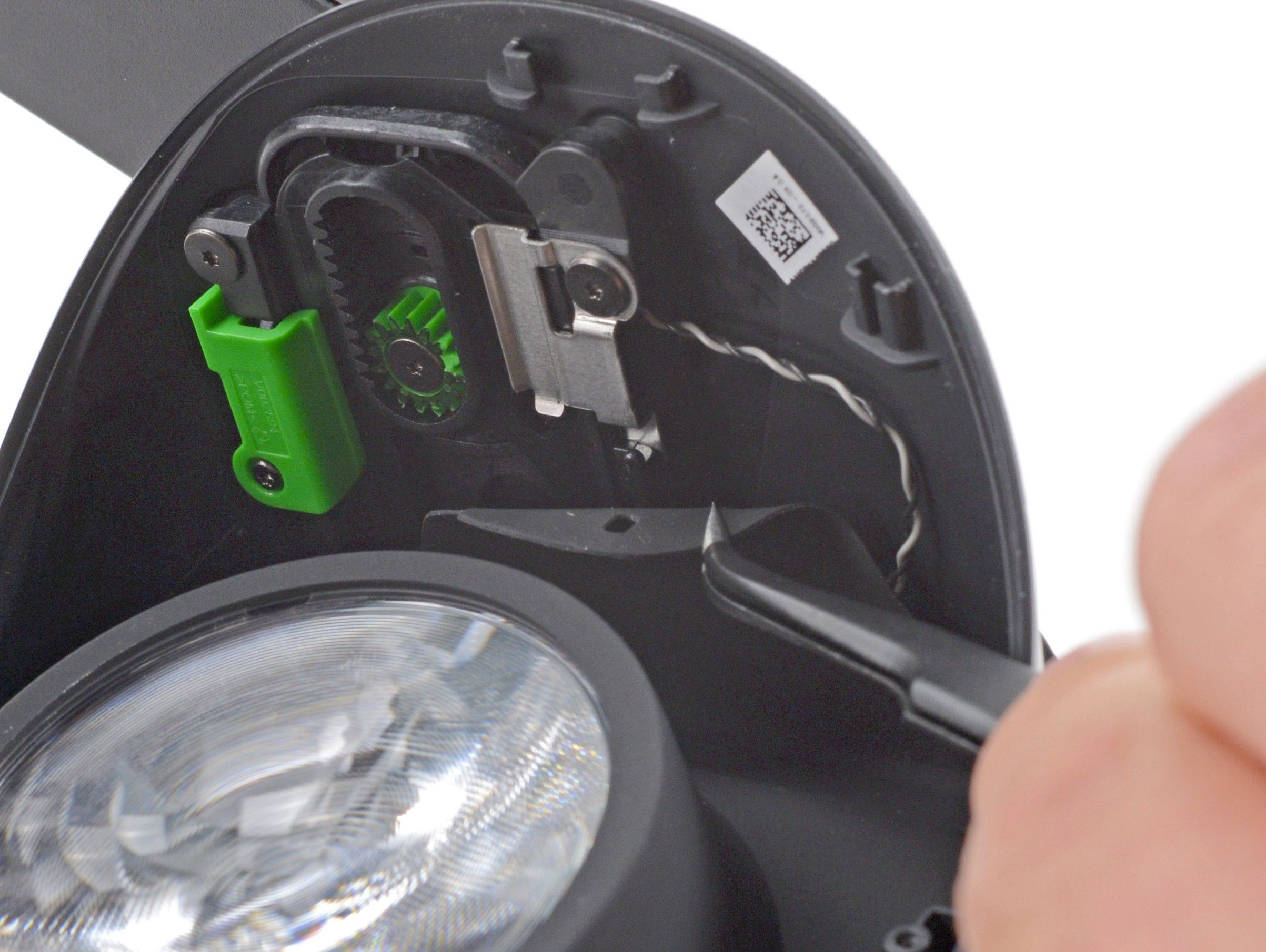
- Guide the LEFT ribbon cable (when looking at the Index from the front) through the small gap between the plastic housing of the Index and the threaded insert, as shown in the pictures.
Make absolutely sure that the ribbon cable is fully pushed through and not stuck in the gap. If the cable gets caught there, it will be permanently damaged beyond repair.
- 12
Installing the Frunk
Route the cables through the new frunk and secure it to the headset.
Read the entire step before you start!
- Avoid sharp bends: The cables must not be sharply bent or creased. A gentle curve, as shown in the photos, is fine.
- Do not pinch the cables: Make sure the ribbon cables are not pinched when attaching the new frunk. They should lie as flat as possible and must not stand on edge, as this could compress and damage them.
This step requires some patience and care, because the cables tend to stand upright or shift out of position.
Sometimes it helps to pre-bend the cables slightly so they naturally fall into the correct position during installation, as shown in the picture.
-
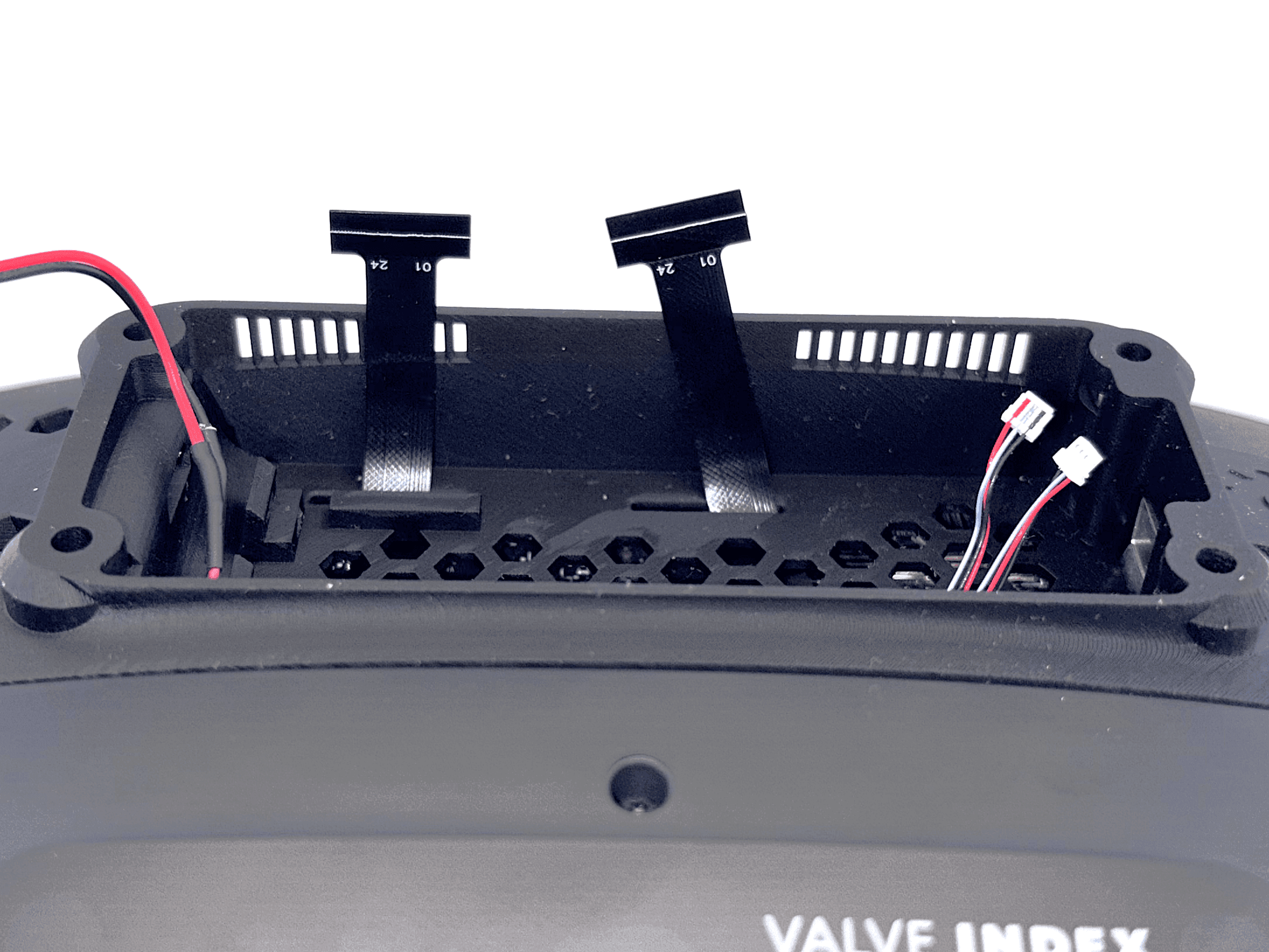
 1 / 2
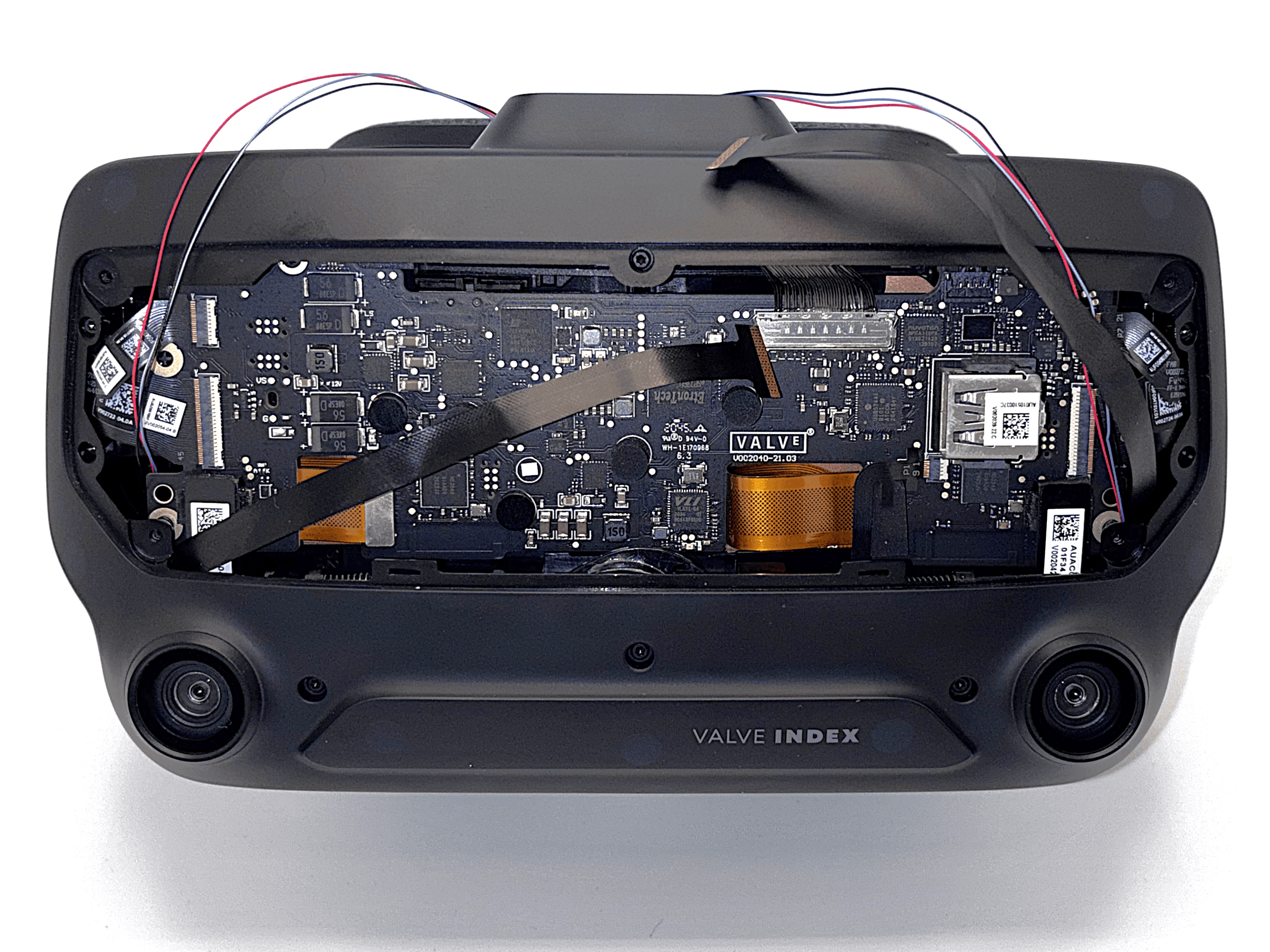
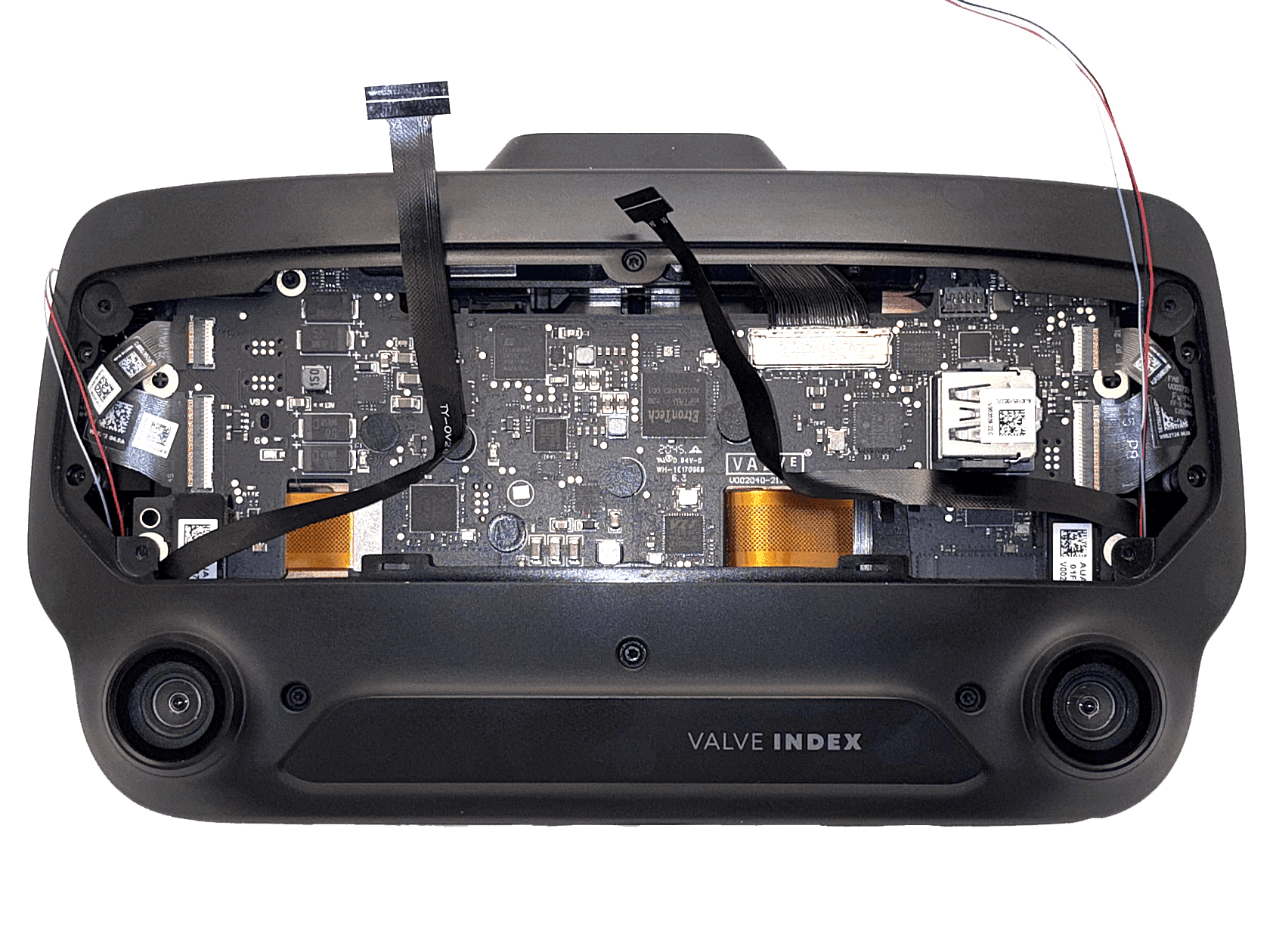
1 / 2When attaching the frunk, make sure the cables run roughly as shown in the pictures. The exact routing is not critical, but it is very important that they are not pinched or sharply bent.
Pay special attention to the right cable near the USB port. In my experience, it tends to stand upright in front of the connector. The cable should route away from the USB port, not in front of it.
You should not feel any significant resistance when placing the new frunk. If you have to use force to push it down, one of the ribbon cables is probably being pinched, most likely the right one when looking at the Index from the front.
-
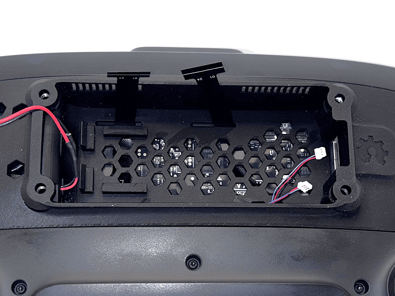 1 / 2
1 / 2The cables should extend about 1 cm beyond the edge of the frunk so you can easily connect them later. The exact length is not critical, as long as there is enough cable to plug them in comfortably.
Before tightening the screws, make sure that no ribbon cable has shifted into the path of a screw (see step 11).
Make sure the gold contact side of the ribbon cables is facing upward when you feed them through the passthrough.
- 13
Installing the Mainboard
Carefully insert the mainboard into the USB connector and secure it in place.
- Insert the mainboard at a slight angle into the USB connector. As soon as it clears the edge of the frunk, level it out so it slides straight into the USB connector.
- Once the board is fully inserted, press down on the back until it clicks into the hook.
Due to manufacturing tolerances, the hook may not always engage cleanly. If it doesn't fit or breaks off, you can ignore it.
- 14
Connect all Cables
Connect the ribbon cables, LED connectors, and fan.
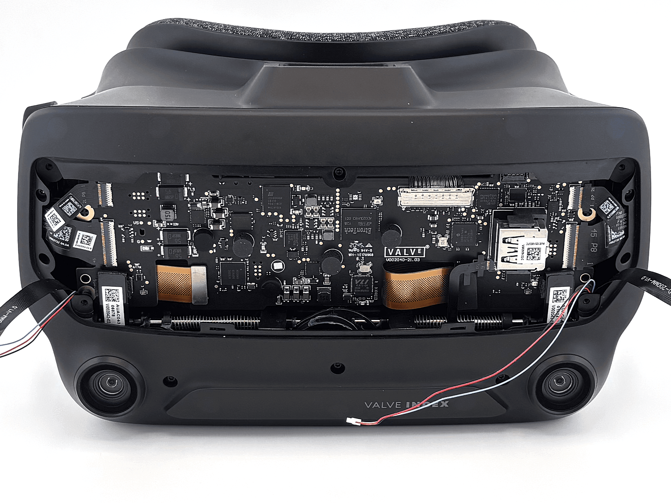
 1 / 5
1 / 5- Connect the ribbon cables. Do not crease them, bend them gently as shown in the picture.
- Open the connectors by lifting the black tabs on the sides upward, as demonstrated in this video.
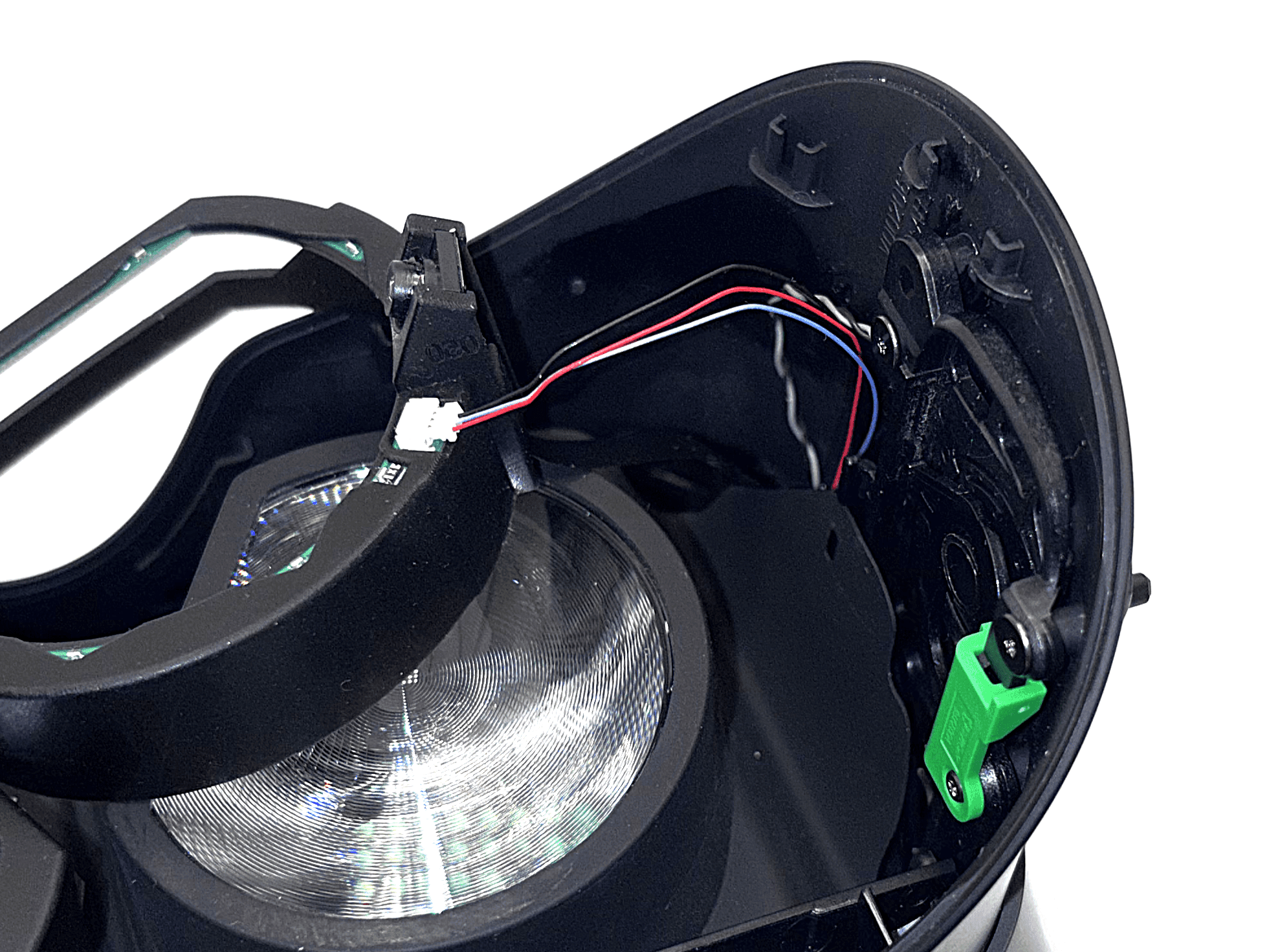
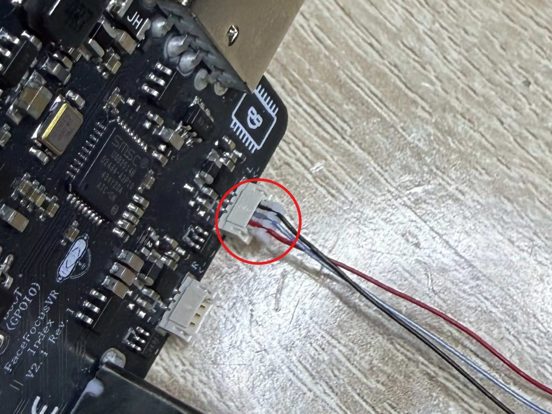
- You can now also plug in the two connectors for the LEDs. Pay attention to the connector's orientation, as it only fits one way, do not force it. The cable colors and wire order do not matter. Just make sure the metal contacts of the connector are facing downward when plugging it in, as shown in the third picture.
- Lastly, plug in the fan.
Make sure the metal contacts of the LED connectors are facing downward when plugging in, it only fits one way, so do not force it.
Always insert all connectors perfectly straight. Never push them in at an angle or tilted to one side. Doing so will bend the delicate metal contact pins and can permanently destroy the board.Once everything is connected, compare your connectors with the following “Reference: Correctly Seated Connectors” block to make sure each one is fully seated.
-
Reference: Correctly Seated Connectors
Before closing everything up, compare your connectors with these reference images. A connector that isn't fully seated is the most common reason a camera doesn't show up later.
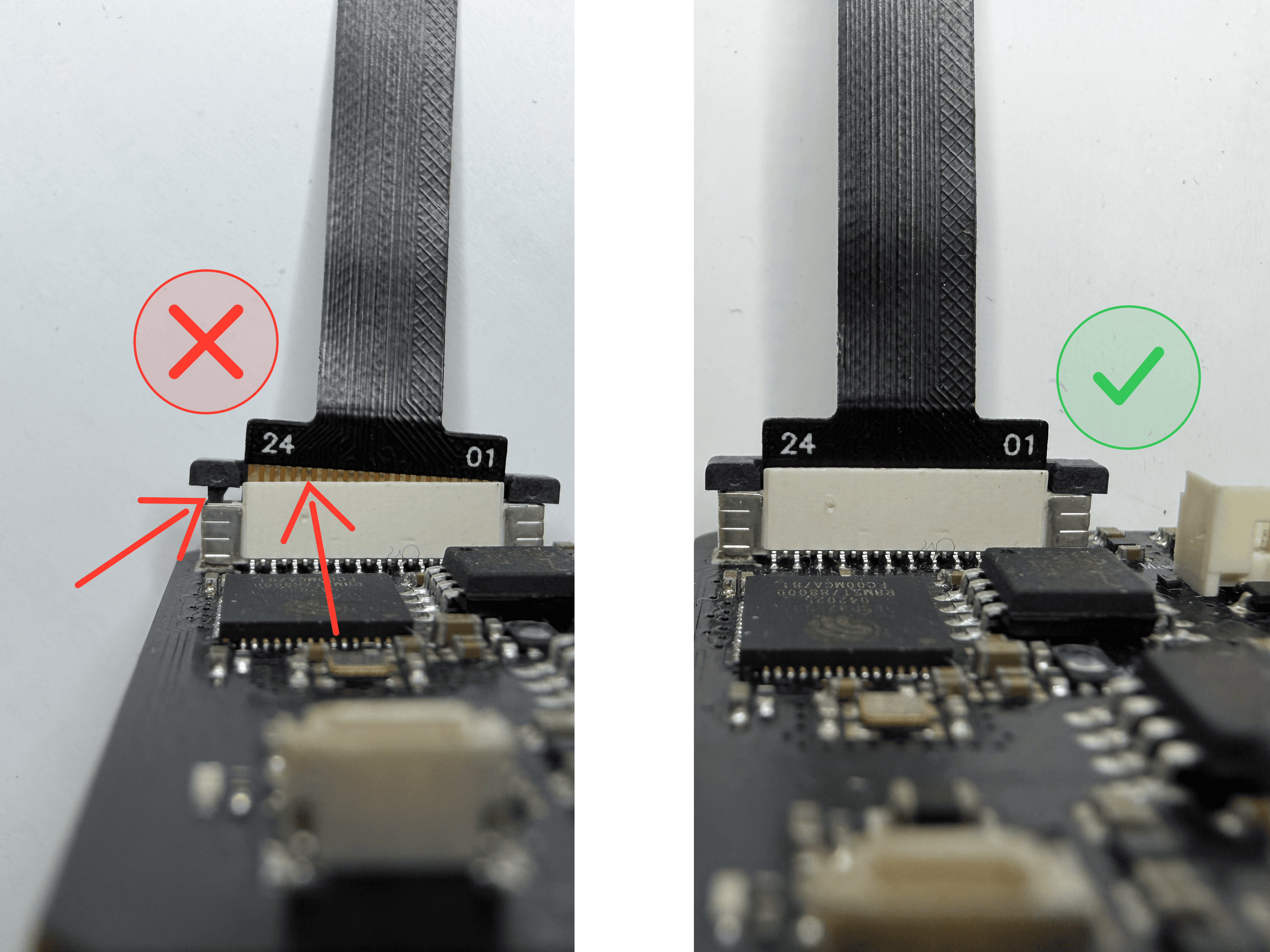
 1 / 2
1 / 2Camera (ribbon) cables: The left side of the image shows how it should not look. Make sure the ribbon cable is pushed all the way into the connector, so that none of the gold contacts are visible anymore. Also check that the locking tabs holding the cable are fully pressed down, with no air gap left.
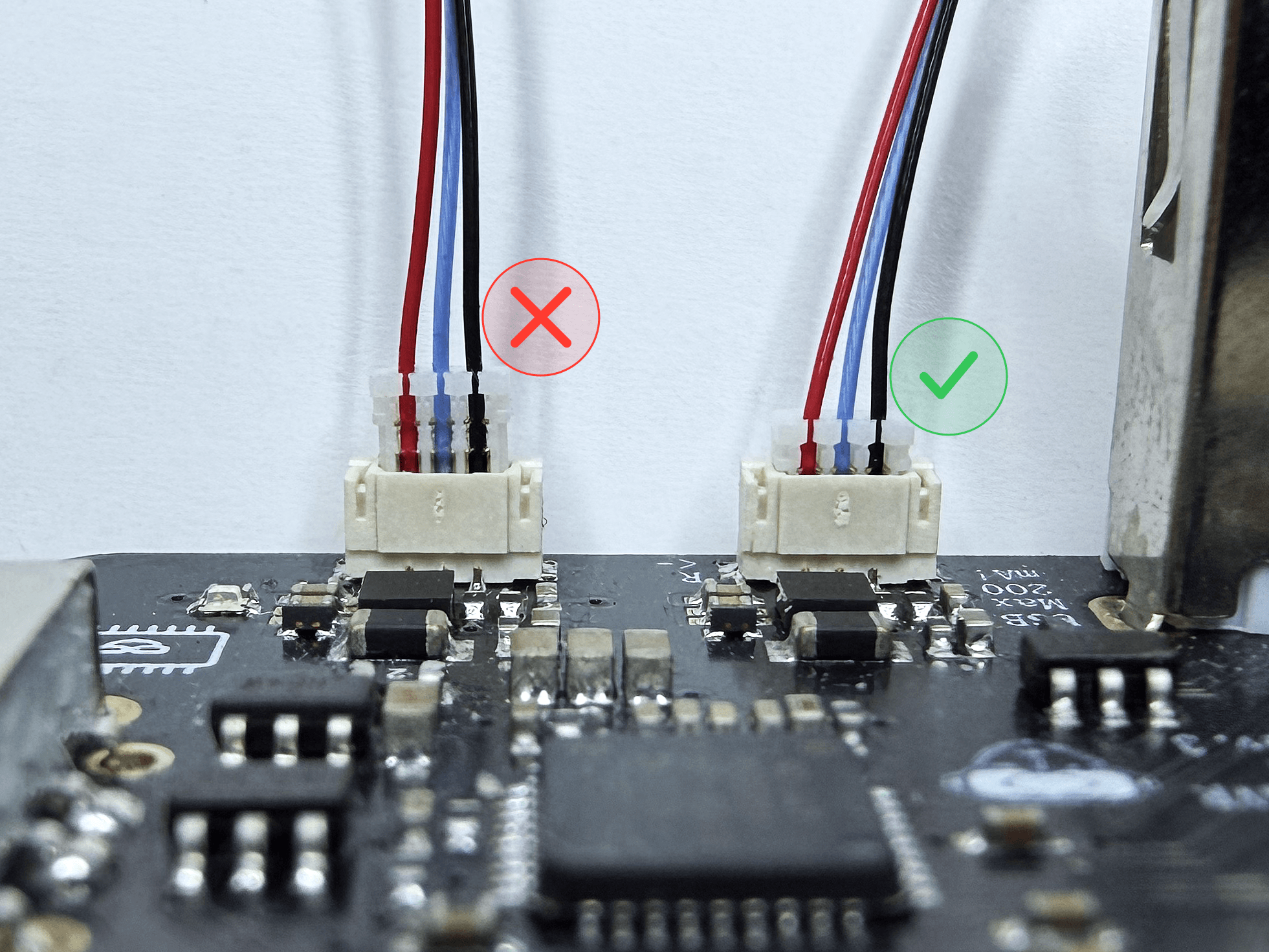
LED connectors: As described in step 14, make sure each connector is straight and correctly oriented when you insert it. The connectors need very little force to seat, so do not force them. Double-check against the pictures and make sure they are fully seated as shown.
- 15
Front Cover
Attach the front cover with the face tracking module and power switch.
 1 / 2
1 / 2- Feed the pre-assembled face tracking module through the front cover and connect it to the board as shown in the photo.
- Connect the power switch to the board.
- Secure the cover using the supplied screws.
You are screwing into plastic, so do not overtighten. A snug hand-tight fit is all that is needed. Applying too much force risks stripping the threads permanently.
- 16
Face Tracking Module Arm
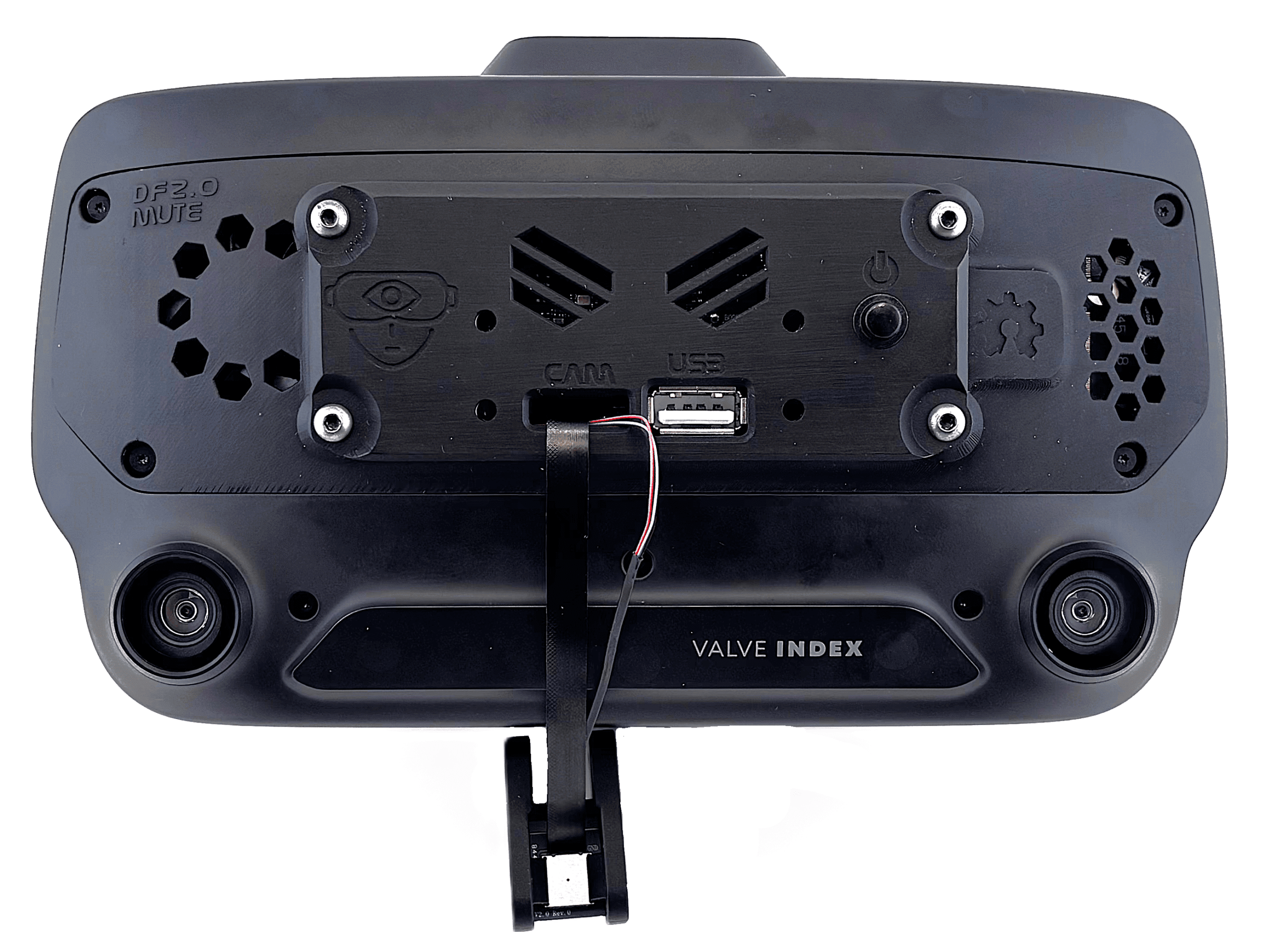
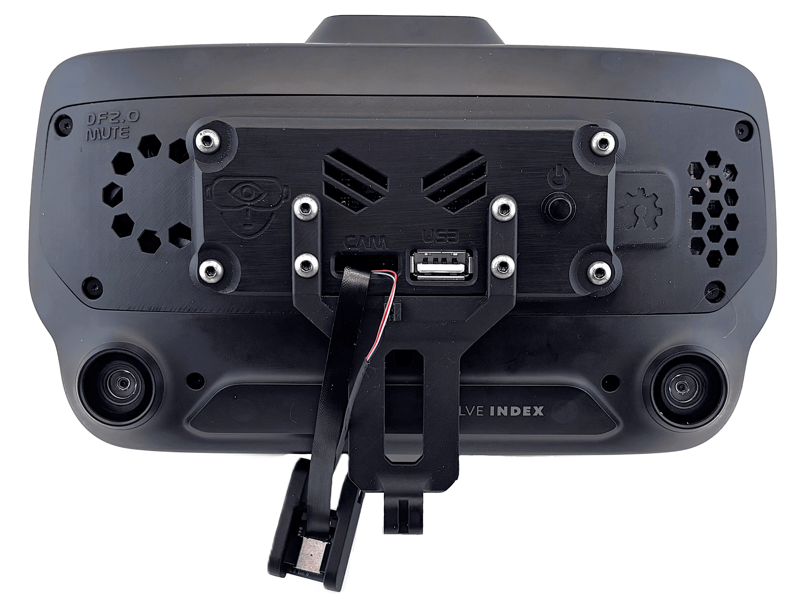
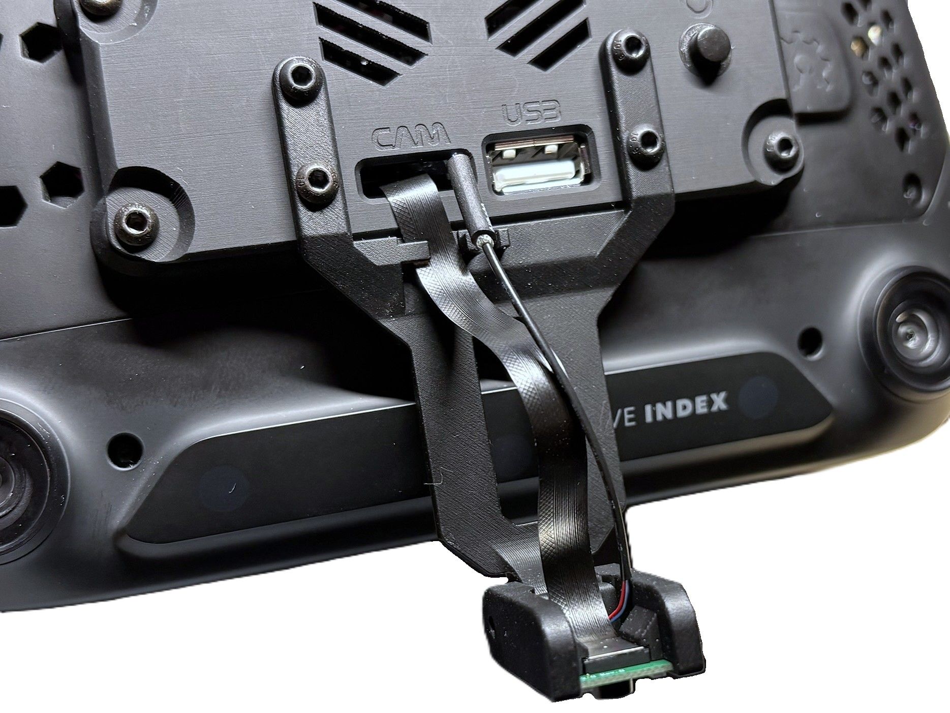
Route the ribbon cable through the holder and mount the arm to complete the installation.
 1 / 3
1 / 3- Feed the ribbon cable through the designated holder and install the arm. The easiest way to do this is to temporarily position the face tracking module at an angle so the cables are not under tension.
- Install the long screw that secures the face tracking module. Looking at the Index from the front, feed the screw in from the left, as shown in the third picture: it passes through the face tracking module and finally threads into the nut on the right. Do not insert it from the right.
- Adjust the module so it points toward your face, then tighten the screw. The installation is now complete.
You are screwing into plastic, so do not overtighten. A snug hand-tight fit is all that is needed. Applying too much force risks stripping the threads permanently.
For the long screw, I recommend tightening it only enough that you can still move the face tracking module easily by hand. Leaving a little play here makes it far less likely that the module's arm breaks off.
-
Congratulations, you are done!
Your hardware installation is complete. Follow the steps below to verify everything is working.
To test if everything is working, power on your Index and switch on your new hardware using the button on the front. A blue LED should light up on the board, visible through the top ventilation slots above the power button.
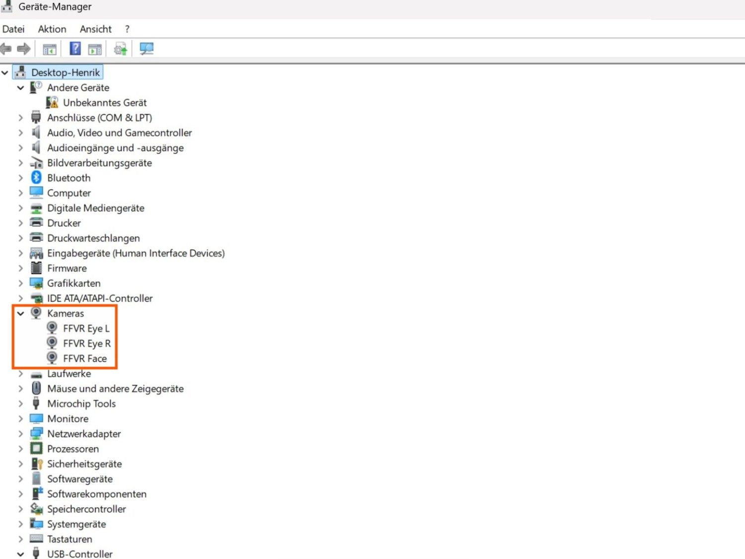
Next, open the Device Manager. If you see three camera devices listed, as shown in the image on the right, the mainboard is working correctly. If you only see two, simply power-cycle the system once. This can happen because Windows or the USB connection may not initialize all devices on the first attempt.
Now open the Windows Camera app and try switching between all three video streams. If this works, congratulations, your hardware is installed and functioning correctly.
Now move on to the software part.
Basics
This project focuses on hardware. Your computer sees the three cameras (Eye L, Eye R, Face) as standard UVC webcam streams at 240x240@60 FPS or 320x320@45 FPS on newer revisions. Any software that can process a webcam stream will work.
Popular tracking software includes ETVR, Ryan's Eye Tracking, and Project Babble. All of them are compatible with this hardware. I recommend Baballonia by Project Babble for the best results and ease of use, but feel free to try other options.
This guide covers the Baballonia setup.
-
VRCFaceTracking
 1 / 3
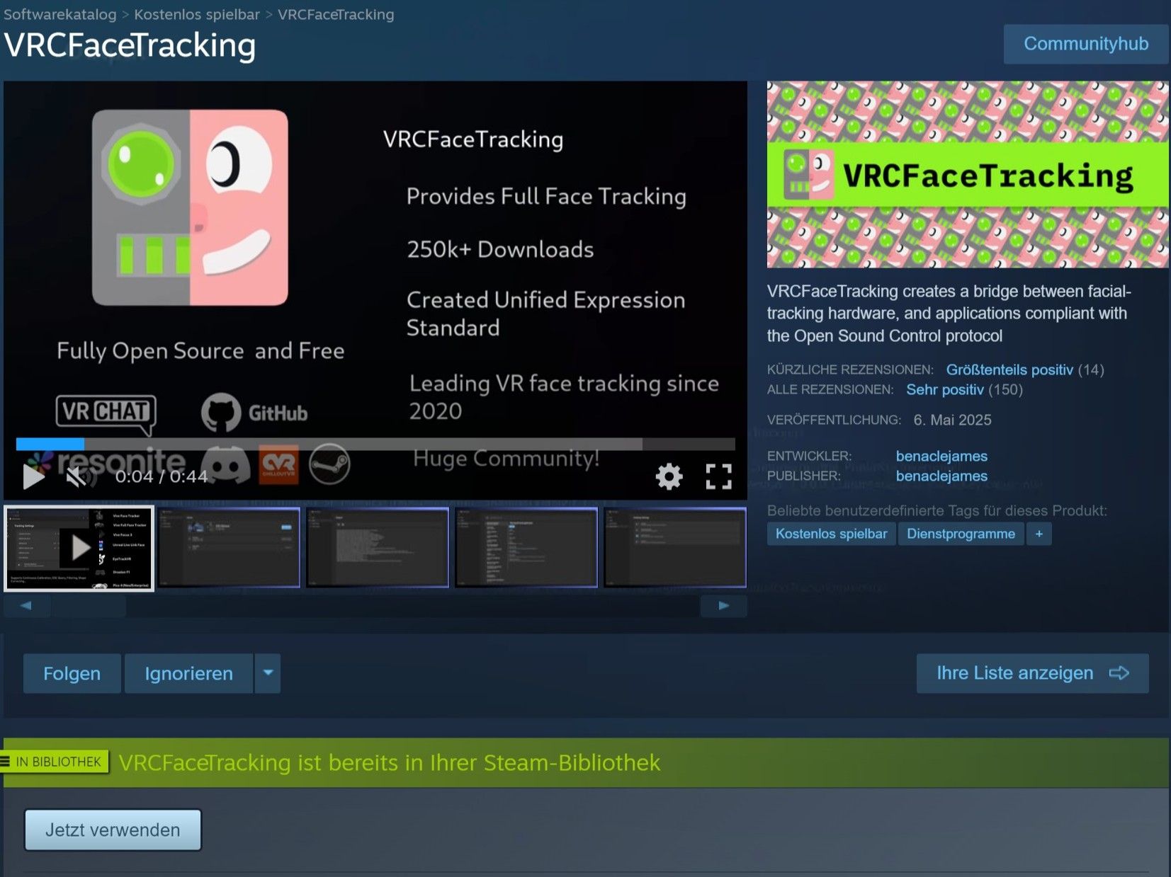
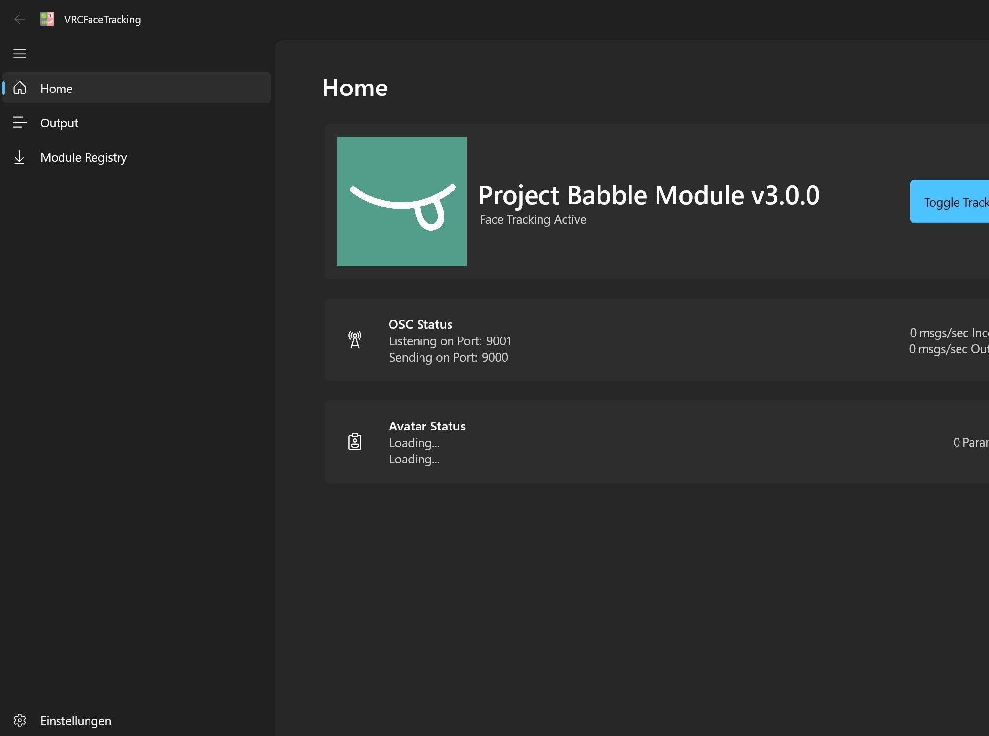
1 / 3VRCFT acts as a translator for VRChat. It converts face-tracking values and eye-tracking data it gets from Baballonia into parameters that VRChat understands, allowing your avatar's expressions and movements to respond accordingly.
If you want to use face tracking (and eye tracking) in VRChat, you will need VRCFT, regardless of whether you are using my hardware or any other face-tracking solution.- Download VRCFT on Steam: store.steampowered.com/app/3329480/VRCFaceTracking
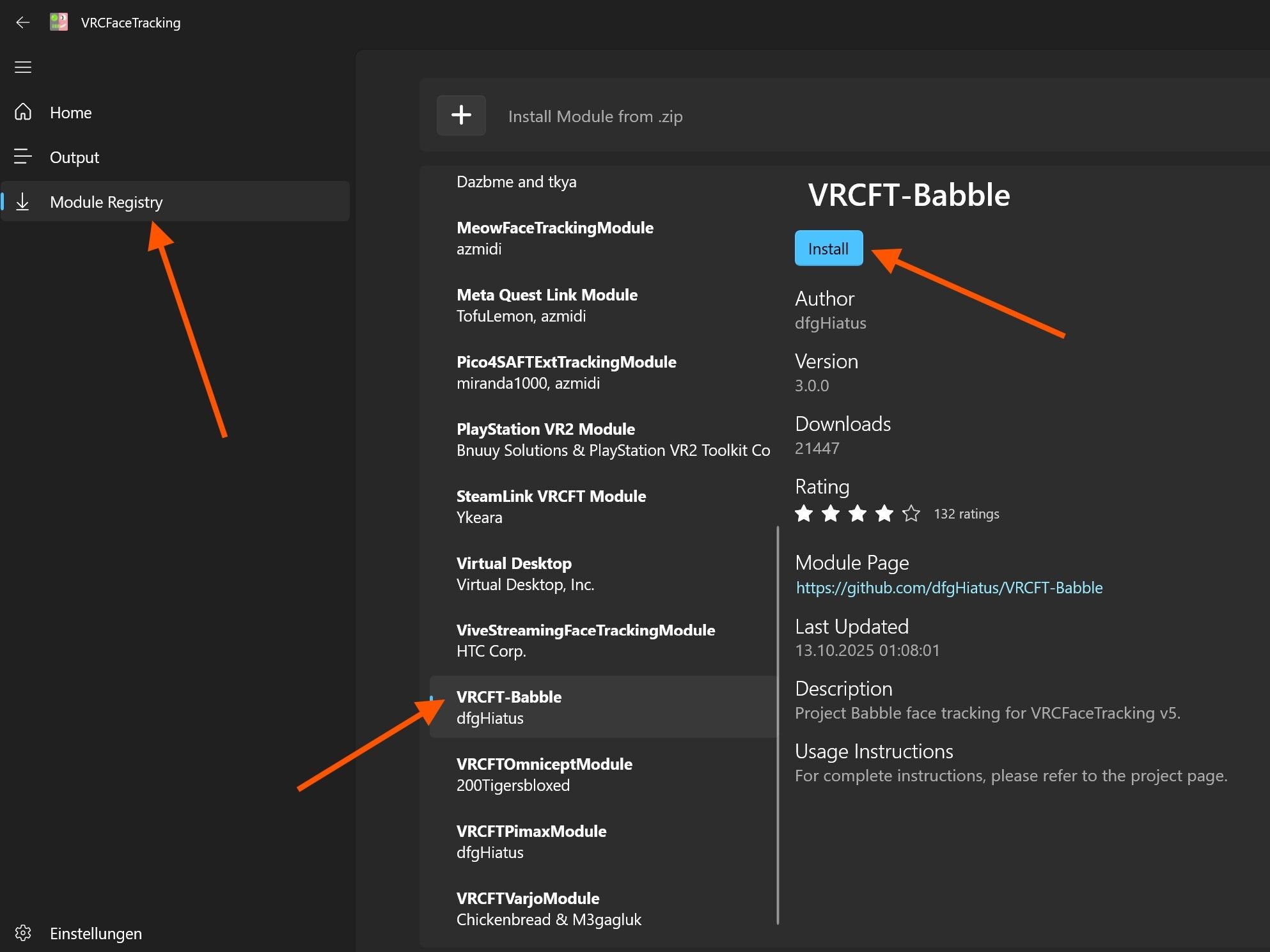
- After launching it, navigate to "Module Registry" and search for the module "VRCFT-Babble", then install it.
- Restart VRCFT.
- The Babble module should now appear on the home page of the VRCFT app, as shown in the last image. No further steps are required in VRCFT.
-
Baballonia
 1 / 5
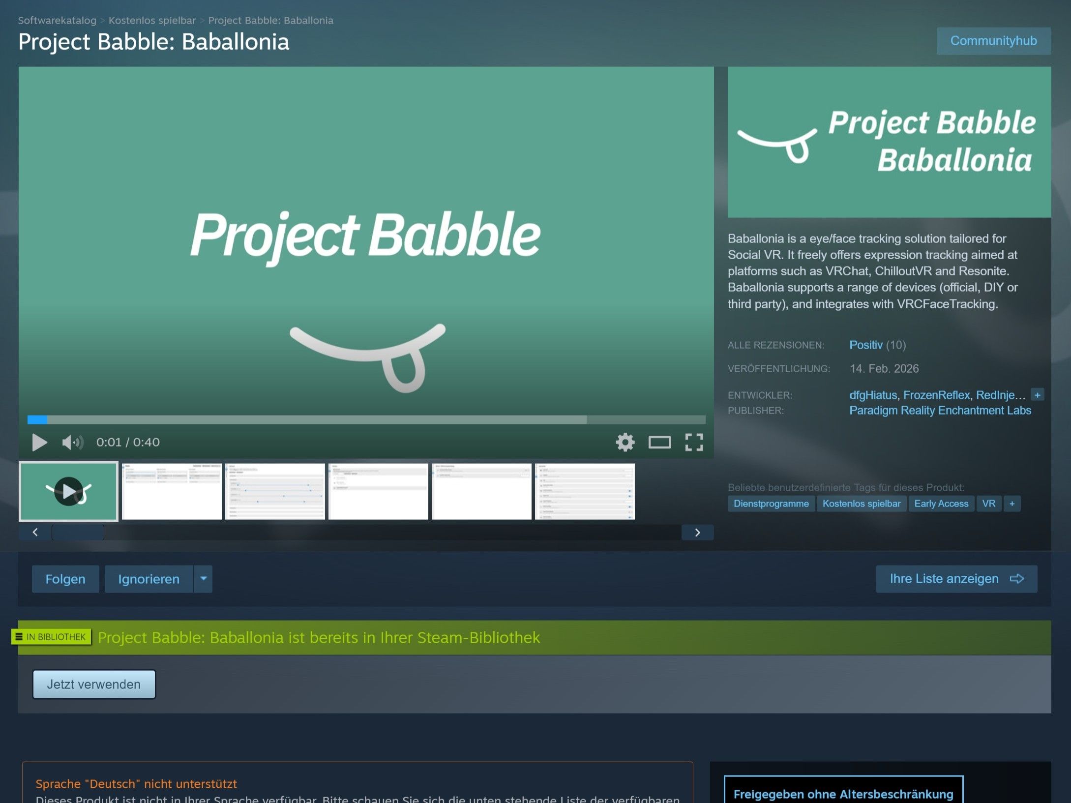
1 / 5Baballonia analyzes the camera streams from your eyes and face to determine your gaze direction, eye openness, and facial expressions, then forwards this data to VRCFT.
- Download Baballonia on Steam: store.steampowered.com/app/4091970/Project_Babble_Baballonia
- Open Baballonia and skip the setup wizard.
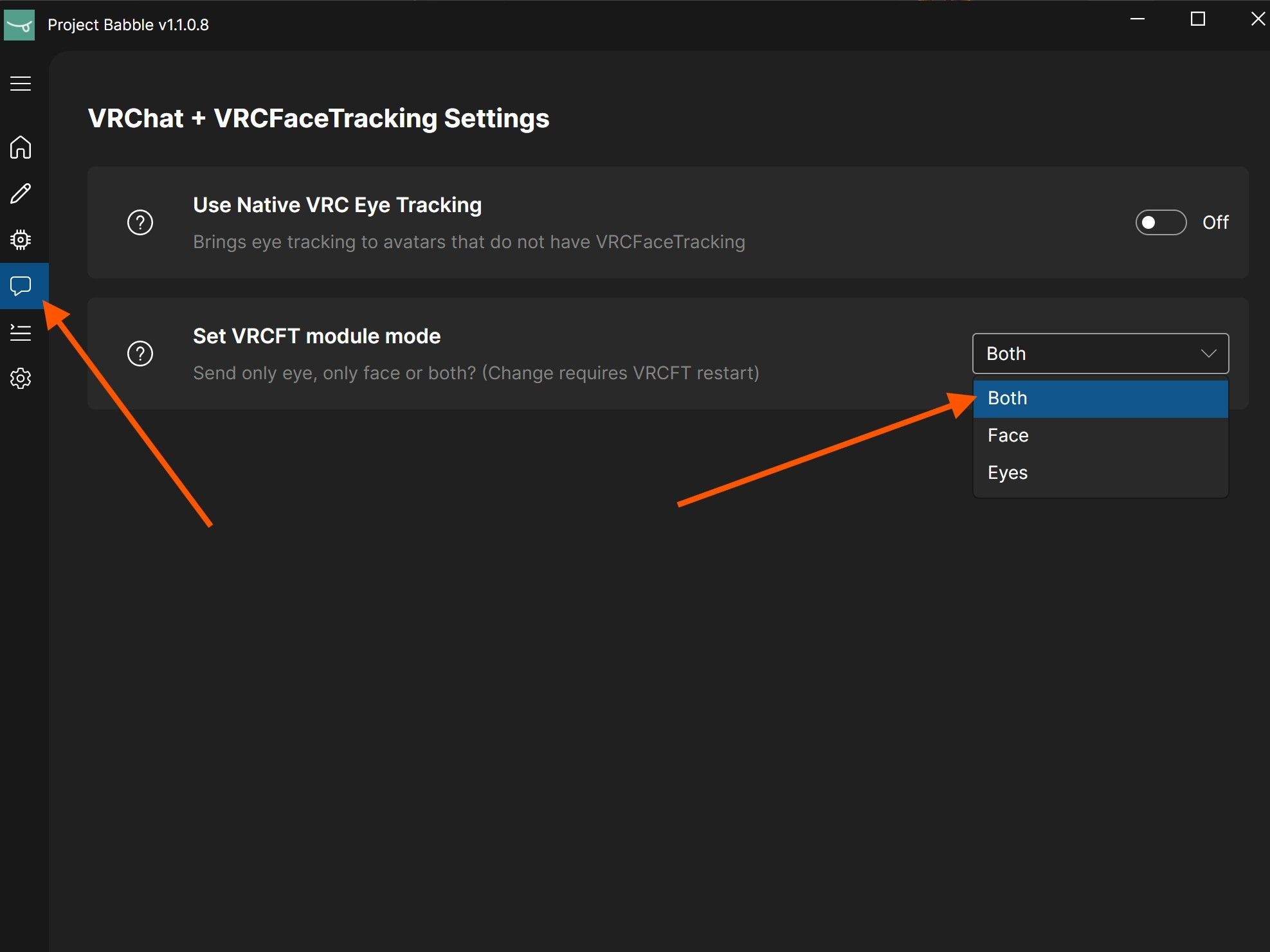
- Open the communication settings and set the VRCFT module mode to "Both" so that both eye and face data are sent. I do not recommend native VRC eye tracking.
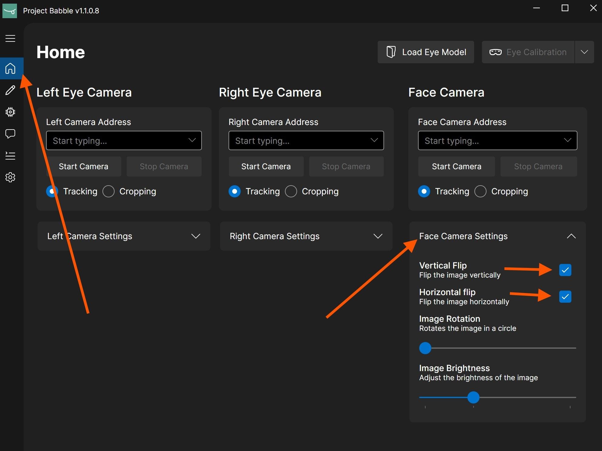
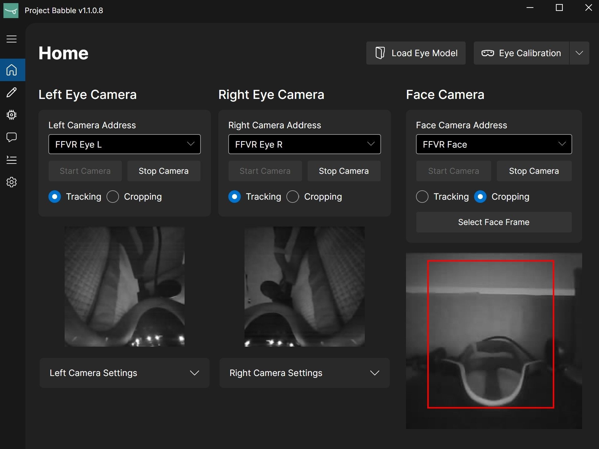
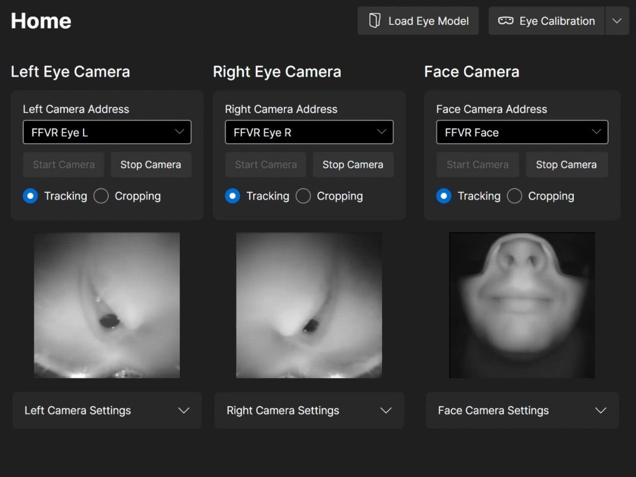
- Open the "Face Camera Settings" and enable both the vertical and horizontal flip options. The flip options may appear as icons depending on your version. Do not adjust any camera settings for the eyes!
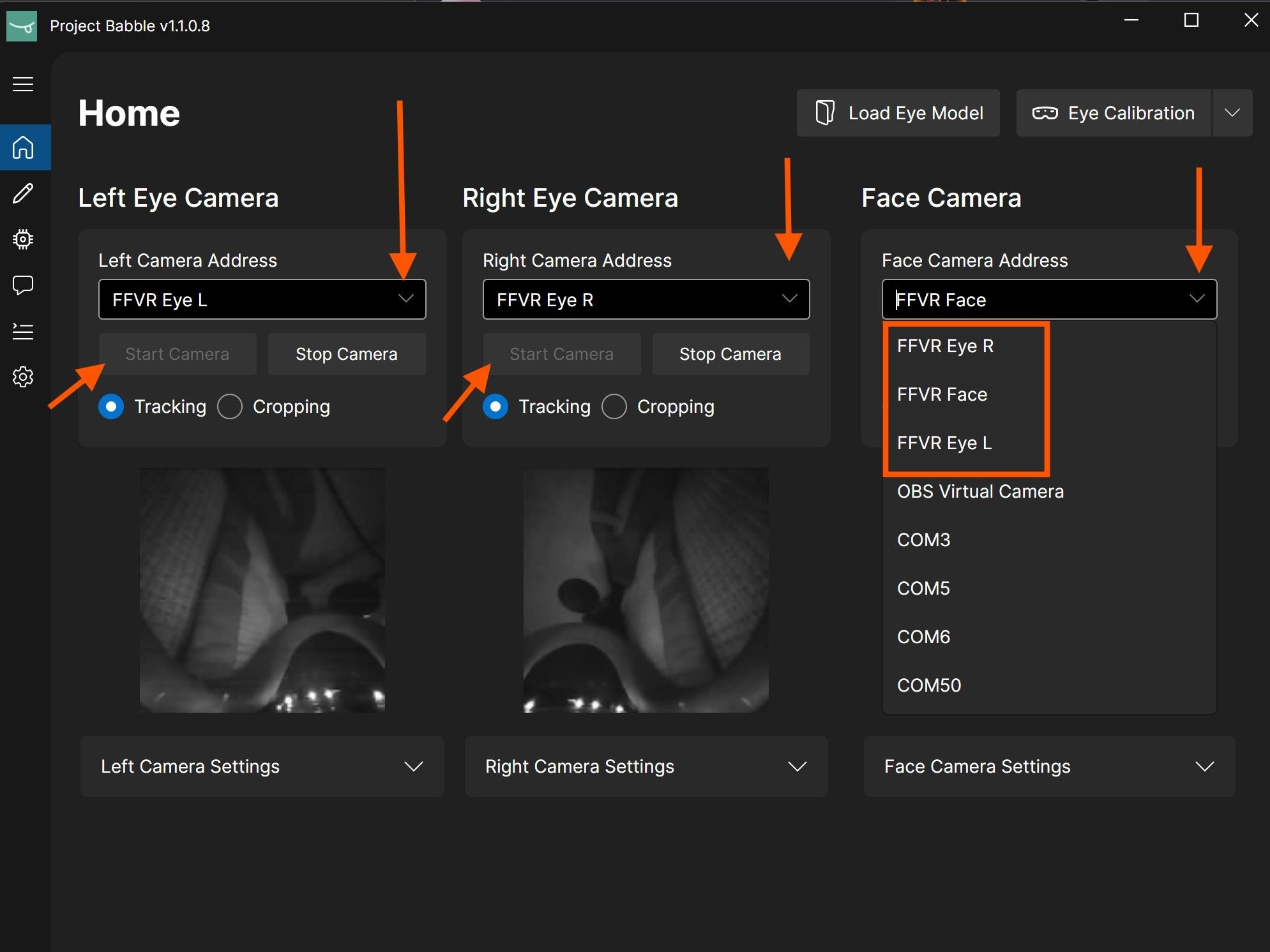
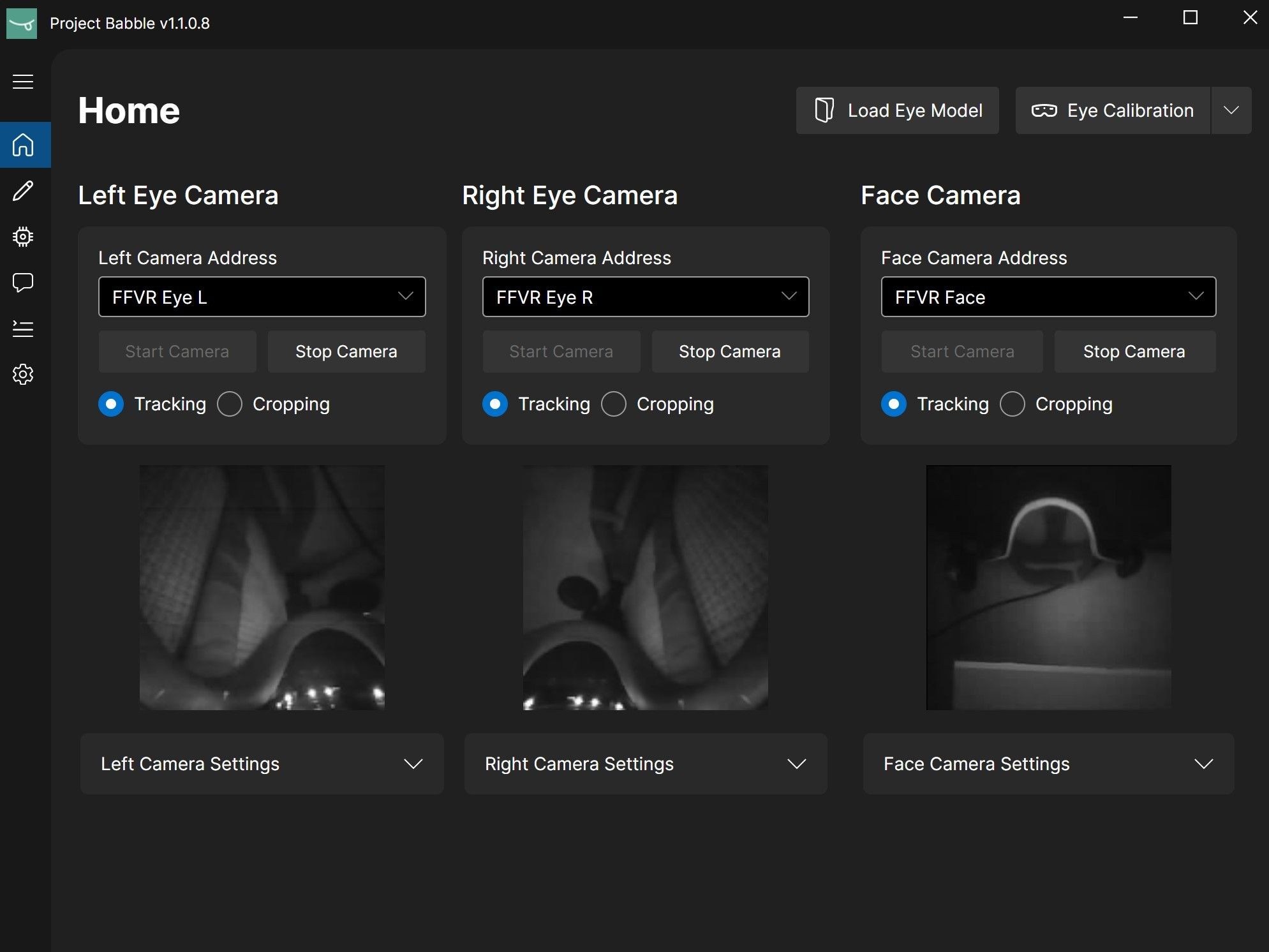
- Make sure your Index and the hardware are powered on, then select the corresponding camera from the dropdown menu.
- Once you've selected all the cameras, click "Start Camera" for each one.
-
Almost done!
All following steps need to be done while you are in VR. Yes, VRChat works too.
If the eye-tracking camera image appears overexposed or washed out, check the Safety page and reach out on Discord if needed.
-
Face Camera Cropping
 1 / 4
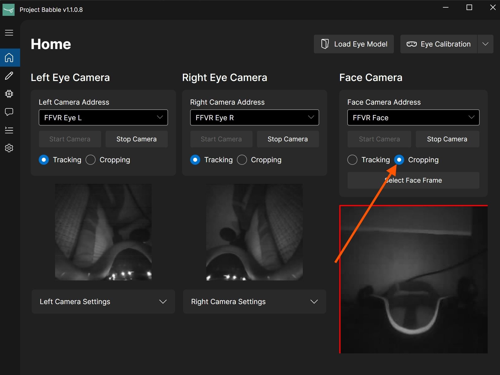
1 / 4For the face camera only, you need to set a crop that keeps your face visible in all extreme positions while including as little background as possible. I recommend the following approach:
- Change the mode for the face camera from "Tracking" to "Cropping."
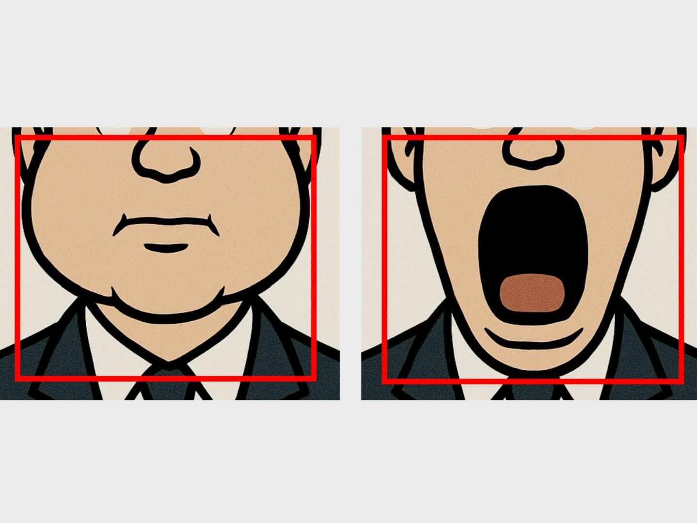
- Puff out your cheeks as much as you can. This sets the side boundaries of the crop.
- Open your mouth as wide as possible. This defines the bottom boundary.
- Set the top boundary so that your nose remains visible, but minimize any static parts of the Index headset in the frame.
- Try to keep the crop box as close to a square shape as possible.
- That's it. Face tracking doesn't need any calibration. It automatically adjusts itself over time. Just use it for a few minutes and it will calibrate on its own.
It doesn't have to be perfectly precise. From my testing, it's better to include a bit more background rather than accidentally cutting off parts of your face. In the end, your crop will likely look similar to mine shown in the last image.
-
Eye Tracking Calibration
 By clicking, you agree to load the video from YouTube. Privacy Policy
I highly recommend watching the video before starting the calibration process.
- Stand in the middle of your playspace facing your forward direction. If you're unsure which way that is, recenter your playspace.
- After clicking "Eye Calibration," a SteamVR overlay will appear showing a short video of the required head movements.
- Once the 60-second timer ends, repeat those head movements for about 3 minutes. The exact order doesn't matter. What's important is that your eyes always stay focused on the ball and that you move your head so your eyes reach their extreme positions.
- When this part is done, you'll receive feedback. Then a message will appear saying: "When the countdown finishes, close your eyes."
- When the timer reaches 2 seconds, close your eyes and keep them fully closed until you receive another confirmation.
- While your eyes are closed, squeeze each eye shut twice and raise your eyebrows twice as if making a surprised expression, keeping your eyes closed the entire time. Moving the headset slightly during this phase can also help.
The goal is to teach the software what your eyes look like when closed, since this can vary depending on facial expression or headset position.
-
You're all set!
Eye and face tracking is now ready to use. Try this avatar for testing in VRChat.
If you want to fine-tune your tracking, fix issues with blinking or winking, or exaggerate certain expressions, switch to the Fine-Tuning tab.
-
Before you start
Only adjust these settings if you notice a specific issue, for example incorrect blinking, expressions triggering too early, or expressions not being strong enough. If everything works fine, there is no need to change anything.
-
Adjusting Parameters
 1 / 2
1 / 2If your avatar isn't blinking correctly, or you want smiles and other expressions to appear more or less intense, you can fine-tune them in the Baballonia app by adjusting the threshold settings.
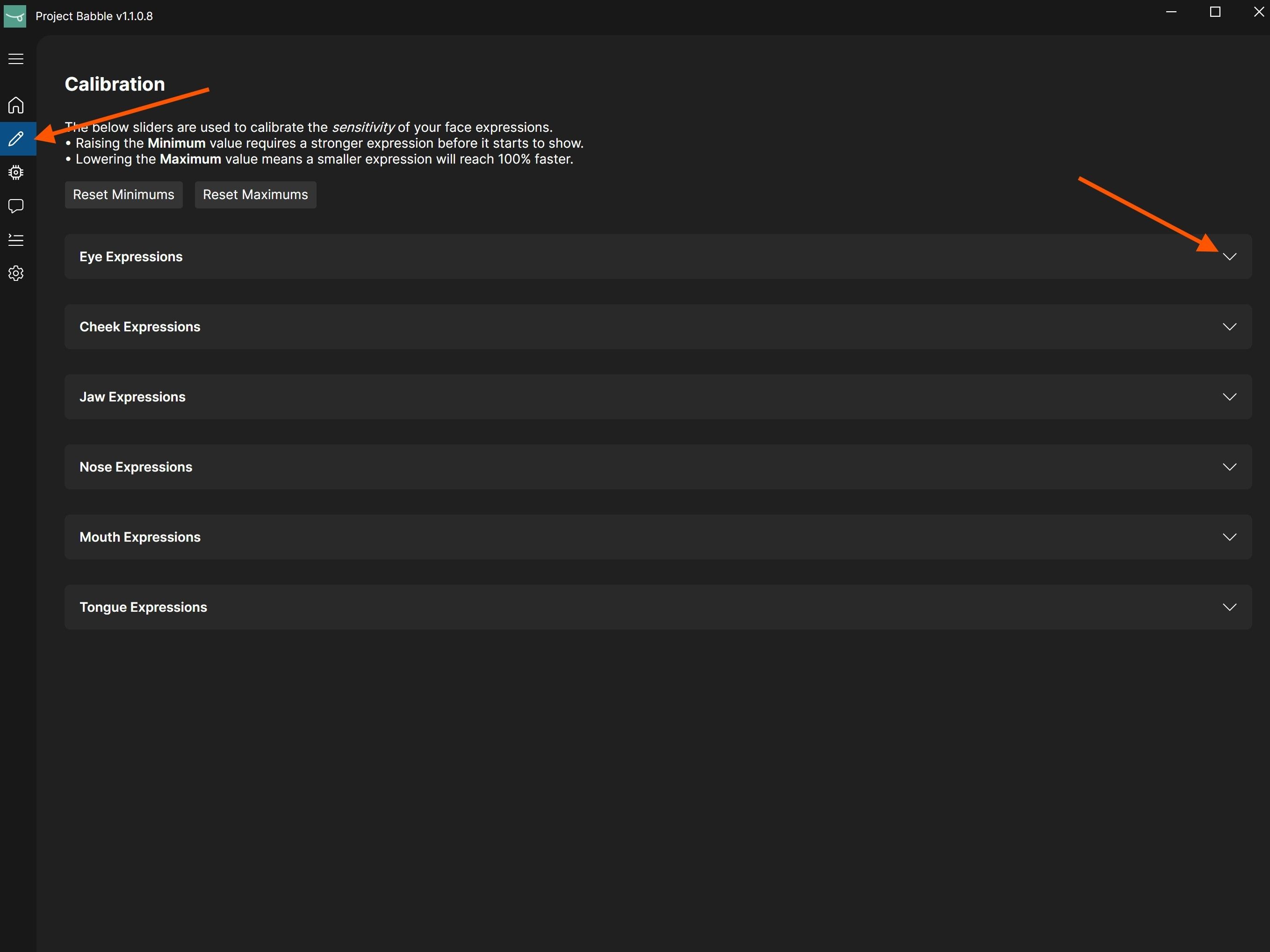
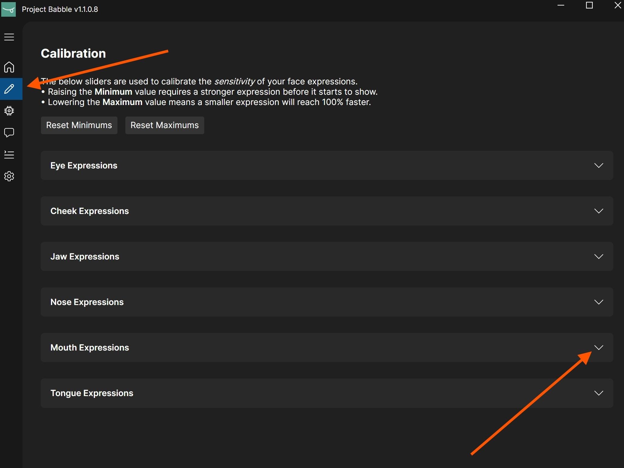
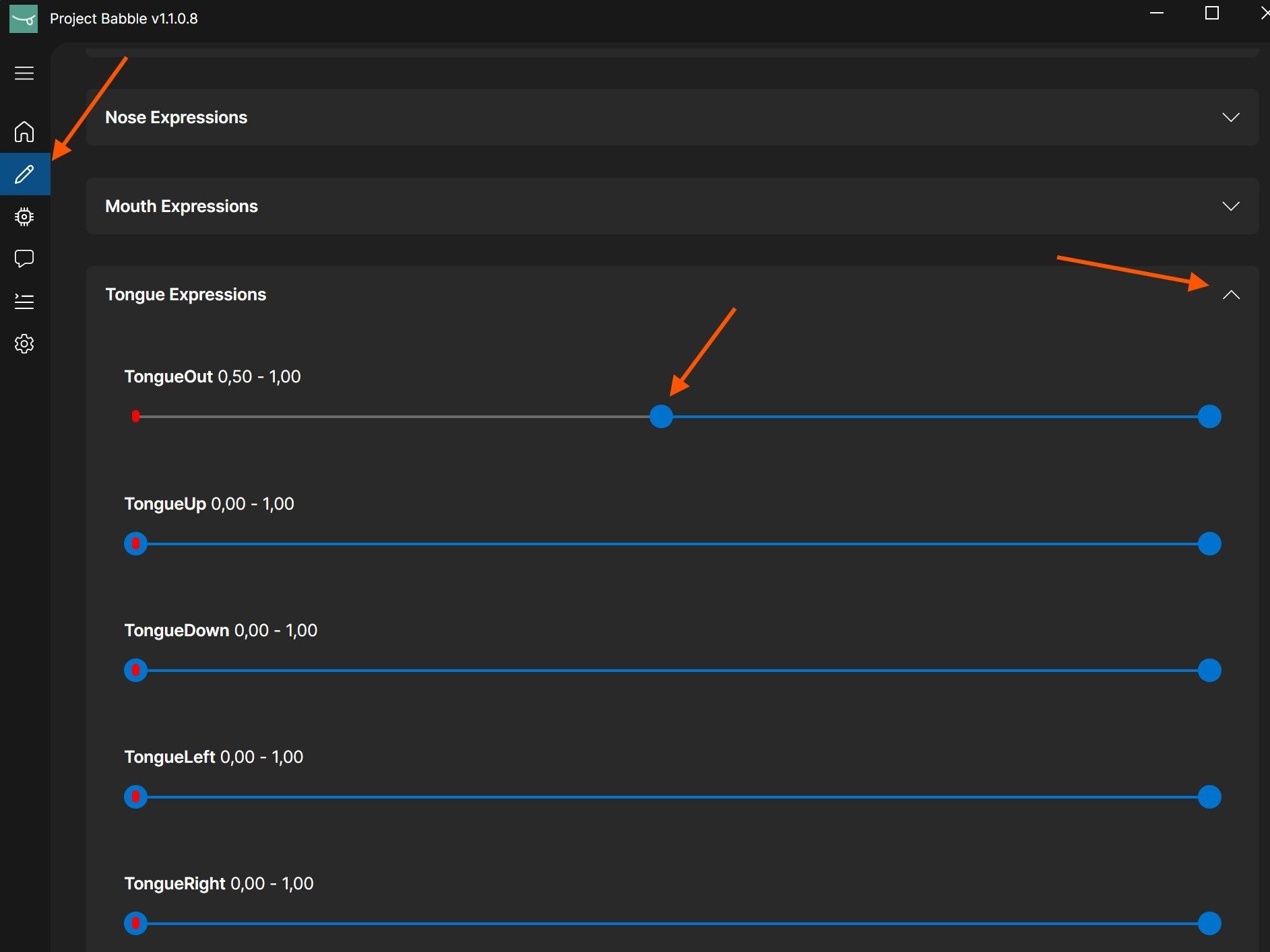
- Navigate to the calibration window in the Baballonia app (pencil icon) and open the parameter group that contains the parameters you want to adjust (for example "smile").
- DO NOT blindly copy my settings, as they are different for everyone. It's better to understand what each slider does to achieve the best results.
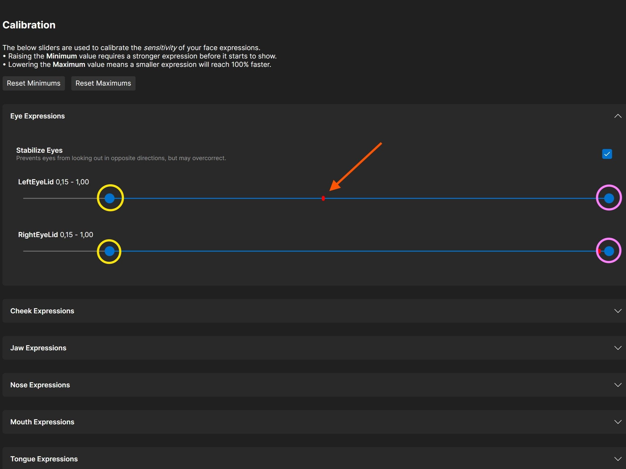
Each parameter, such as LeftEyeLid, RightEyeLid, or any face parameter like smile, has two controls: a minimum (circled in yellow) and a maximum (circled in pink). The red dot shows the current state and moves based on your expression. For example, when your face is relaxed it moves to the left, and when you start smiling it moves to the right.
The minimum value defines when a shape starts activating. Raise it if the shape triggers too early or stays active while idle. The maximum value controls how far the shape can move. Lowering it exaggerates the motion within the new range.
-
Blinking / Winking
 1 / 2
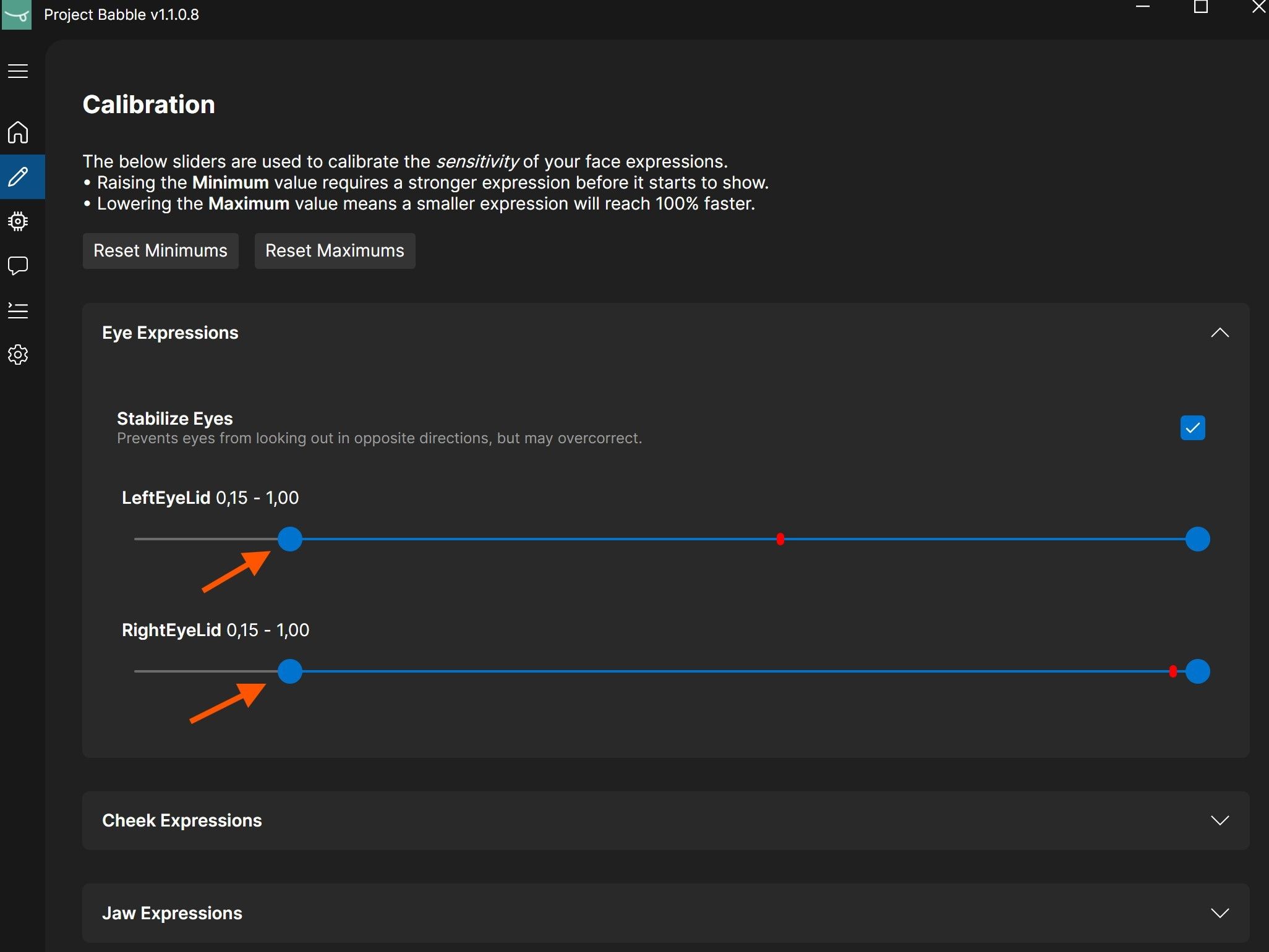
1 / 2If your avatar's blinking or winking doesn't behave as expected, or it doesn't blink at all, you can raise the minimum value of the eyelids. This makes the blink trigger earlier and appear faster.
- Blink several times and watch how far the red indicator moves to the left.
- Move the left minimum slider to that position, or slightly to the right of where the red indicator reaches.
The value will likely be higher than the one shown in the image. Based on the calibration, mine is normally between 0.15 and 0.4.
-
Exaggerated Expression
 1 / 2
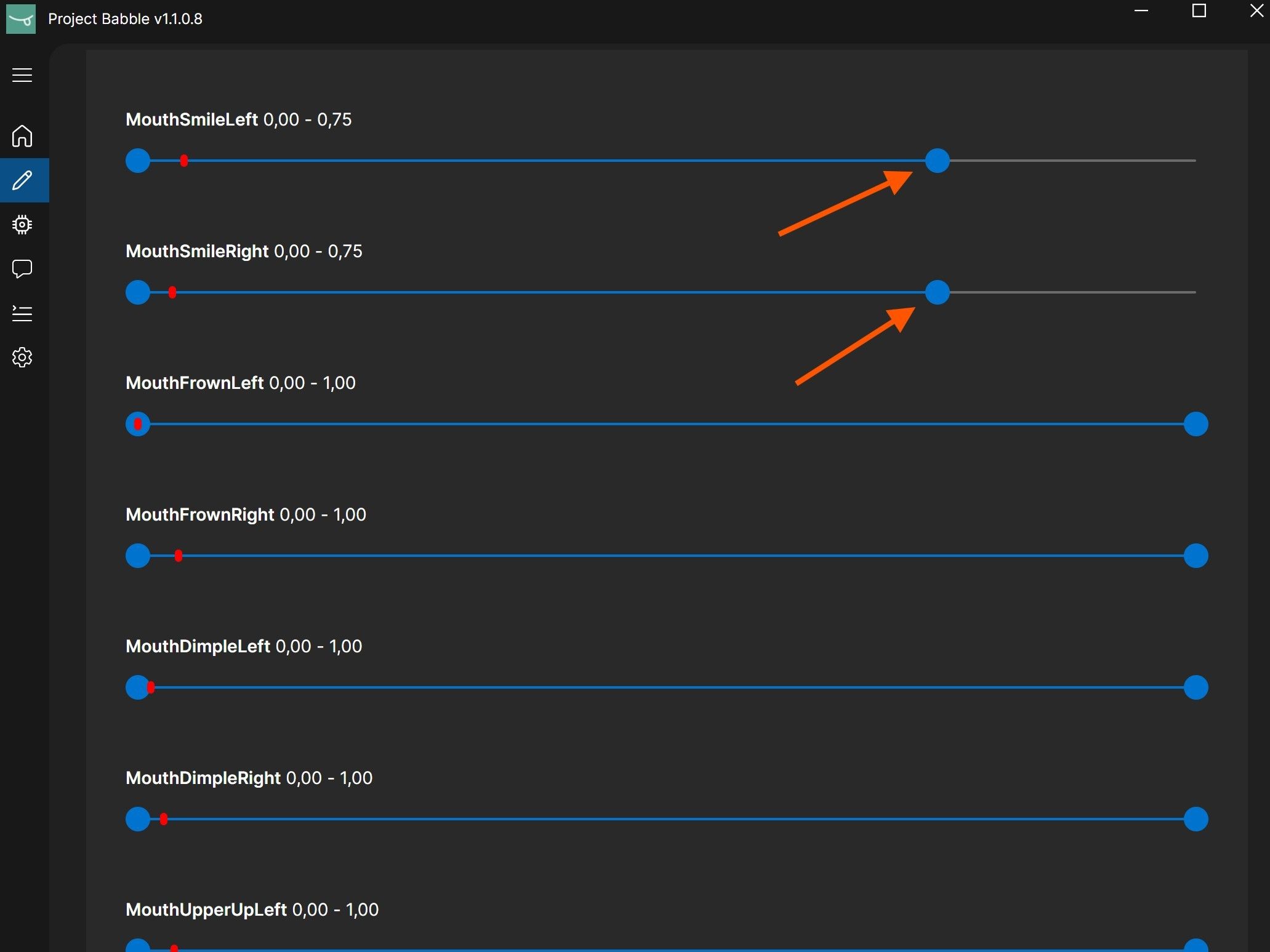
1 / 2Sometimes you may want an expression to trigger earlier, stay slightly active all the time, or be exaggerated.
A good example is smiling. If you want your avatar to keep a slight smile even when your face is mostly relaxed, simply lower the maximum value for the smile parameter.
I highly recommend just playing VRChat with your avatar, looking in a mirror, and experimenting with the parameter minimums and maximums. The values update live, so you don't need to switch between tabs to see the results.
-
Expression Triggering Too Early
Sometimes an expression might trigger too early, for example when you open your mouth and your avatar sticks out the tongue even though you are not actually doing that.
In those cases, you can adjust the minimum value of the corresponding parameter so the expression only activates when it should.
I highly recommend just playing VRChat with your avatar, looking in a mirror, and experimenting with the parameter minimums and maximums. The values update live, so you don't need to switch between tabs to see the results.
What is FFVR Connect?
FFVR Connect is a web-based tool that lets you interact with your FaceFocusVR hardware directly from your browser. You can adjust the fan speed, change LED brightness, enable and read logs, and in the future also perform firmware updates.
The tool is designed to be intuitive and easy to use. Simply open it in your browser, connect your board, and you are ready to go.
You can access it here: connect.facefocusvr.com
Browser & Connection
FFVR Connect requires a Chromium-based browser (Google Chrome, Microsoft Edge, Brave). I recommend Google Chrome. Firefox and Safari are not supported.
If your board cannot connect, it is most likely running an older firmware version that does not support the tool. Every board shipped before 15.03.2026 does not have the necessary hardware for fan control, so a manual firmware update is not needed.
If you still feel the need to update, please reach out via Discord.
Features
Fan Speed - The default is 30%, which is also what I recommend. Do not set it below 25%.
LED Brightness - Can be changed, but this is not required. Only adjust if specifically asked by FaceFocusVR support.
Logging - Enable and read device logs for diagnostics.
Firmware Updates - Will be available through FFVR Connect in the future.